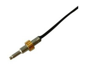
0ZRC0015FF1E Telecom Thermistor PPTC Resettable Fuse TRG015 With Rated Voltage 600V Hold Current 0.15A
Features
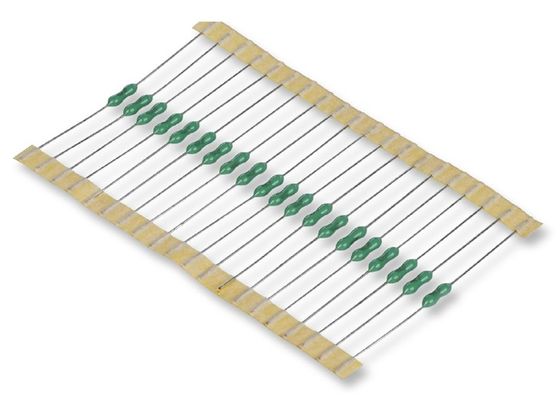
• Radial Leaded Devices
• Maximum 600 VAC interrupt fault rating
• Available in matched resistance “bins”
• Ability to withstand lightning surges
• RoHS compliant
• Resettable overcurrent protection
• Fast time-to-trip
• Agency recognition: UL, CSA, TÜV
• Resistance-sorted and matched devices available
• Low parasitic capacitance/flat impedance with frequency
______________________________________________________________________________ Download________
Electrical Perforamces
| P/N |
Hold Cu. |
Trip Cu. |
Max Volt |
Max Current |
Impulse Volt. |
Max.Trip |
Power |
Resistance(Ω) |
| IH, (A) |
IT,(A) |
Vmax,(v) |
Imax,(A) |
Vmax, (V) |
(A) |
(Sec.) |
Pd typ(W) |
Rmin |
Rmin |
R1max |
| TRG011 |
0.11 |
0.22 |
250 |
3.0 |
600 |
1.00 |
4.0 |
1.0 |
7.0 |
14.0 |
26.0 |
| TRG015 |
0.15 |
0.30 |
250 |
3.0 |
600 |
1.00 |
5.0 |
1.0 |
6.0 |
12.0 |
22.0 |
| TRG016 |
0.16 |
0.32 |
250 |
3.0 |
600 |
1.00 |
7.5 |
1.7 |
4.0 |
10.0 |
18.0 |
Dimension (mm)
| P/N |
A |
B |
C |
D |
E |
Physical Characteristics |
| Max. |
Max. |
Typ. |
Min. |
Max. |
Style |
Lead Φ mm |
Material |
| TRG011 |
9.0 |
12.5 |
5.1 |
7.6 |
4.6 |
1 |
0.6 |
CU |
| TRG015 |
9.0 |
12.5 |
5.1 |
7.6 |
4.6 |
1 |
0.6 |
CU |
| TRG016 |
9.0 |
12.5 |
5.1 |
7.6 |
4.6 |
1 |
0.6 |
CU |
Thermal Derating Chart – I hold (Amps)
| P/N |
Ambient Operating Temperature |
| -40℃ |
-20℃ |
0℃ |
25℃ |
40℃ |
50℃ |
60℃ |
70℃ |
85℃ |
| TRG011 |
0.22 |
0.19 |
0.17 |
0.14 |
0.11 |
0.10 |
0.07 |
0.07 |
0.06 |
| TRG015 |
0.24 |
0.21 |
0.18 |
0.15 |
0.12 |
0.11 |
0.08 |
0.08 |
0.06 |
| TRG016 |
0.25 |
0.22 |
0.19 |
0.16 |
0.13 |
0.12 |
0.08 |
0.09 |
0.07 |
BENEFITS
• Choice of many product options helps engineers by improving design flexibility
• Compatible with high-volume electronics assembly
• Assist in meeting regulatory equipment requirements
• Help improve line balance
• Applicable for legacy POTS and modern digital communications equipment
APPLICATIONS
• Modems
• Phone sets
• Fax machines
• Phone wall outlets
• Alarm systems
• PBX systems
• MDF modules
• Analog and digital line cards
• T1/E1 equipment
• xDSL modems and splitters
• Powered ethernet systems
• VoIP (Voice over Internet Protocol) equipment
• LAN, WAN equipment
• Customer premise equipment
• Access network hardware
Application Guide for Telecommunications and Networking Devices*
To use this guide, follow the steps below:
1. Select your equipment type from the guide below.
2. Select the type of protection depending on the agency and regional specifications in the second column.
3. Select the form factor for your application.
4. Use the Agency Specification/ PolySwitch Device Selection Guide on the next page to select a specific part number for each application based on the agency requirements.
5. Parts with fast time-to-trip or low resistance are available. Please consult a PolySwitch representative.
Environmental Characteristics
Operating/Storage Temperature........................... -40 °C to +85 °C
Maximum Device Surface Temperature
in Tripped State ................................................. 125 °C
Passive Aging................................ +60 °C, 1000 hours............................ ±15 % typical resistance change
Humidity Aging............................. +60 °C, 90 % R.H. 1000 hours ................ ±15 % typical resistance change
Solvent Resistance............................ MIL-STD-202, Method 215B................................. No change Lead
Solderability................................................. ANSI/J-STD-002
Flammability ......................................... IEC 695-2-2 .......................................................... No flame for 60 secs.
Vibration ........................................... MIL-STD-883C, Method 2007.1, Condition A ....... No change
Test Procedures And Requirements For Model TRG Series
Test Test Conditions Accept/Reject Criteria
Visual/Mech.................................. Verify dimensions and materials ........................... Per MF physical description
Resistance..................................... In still air @ 23 °C.................................................... Rmin ≤ R ≤ Rmax
Time to Trip.................................... 1 A, Vmax, 23 °C ..................................................... T ≤ max. time to trip (seconds)
Hold Current .................................. 30 min. at Ihold ....................................................... No trip
Trip Cycle Life.................................. Vmax, Itrip, 100 cycles.......................................... No arcing or burning
Trip Endurance ............................... Vmax, 24 hours..................................................... No arcing or burning

 Your message must be between 20-3,000 characters!