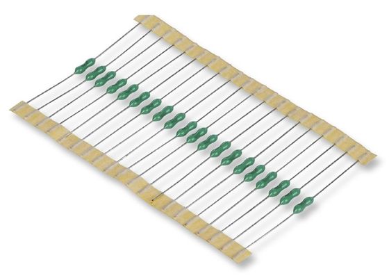
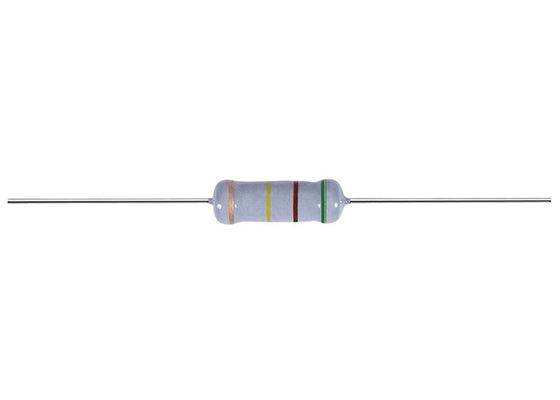
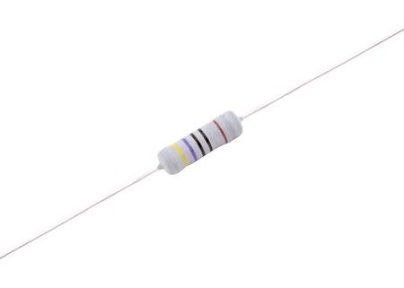
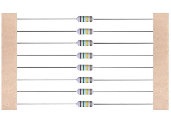
Flame-proof Non-Inductive KNP 0.25-10W Fusible Wire Wound Resistor 0.1-1000 Ohm ±5% With Smaller Size Available
External dimensions (Unit:mm)
P type
The 5th color band; KNP type in ‘Black’, NKNP type in ‘Green’
| Type | Dimensions | |||||
|
Normal Size |
Small Size |
I±2.0 | L±1.0 | ψD | ψd±0.05 | H±2.0 |
|
KNP1/2W, NKNP1/2W |
KNP1WS, NKNP1WS |
60 | 9.0 | 3.2±0.5 | 0.50 | 28 |
|
KNP1W, NKNP1W |
KNP2WS,NKNP2WS | 60 | 11.5 | 4.5±1.0 | 0.68 | 25 |
| 73 | 11.5 | 4.5±1.0 | 0.68 | 31 | ||
|
KNP2W, NKNP2W |
KNP3WS,NKNP3WS | 60 | 15.5 | 5.0±1.0 | 0.68 | 23 |
| 81 | 15.5 | 5.0±1.0 | 0.68 | 33 | ||
|
KNP3W, NKNP3W |
KNP5WS, NKNP5WS |
94 | 17.5 | 6.0±1.0 | 0.68 | 38 |
| KNP5W,NKNP5W | 94 | 24.5 | 8.0±1.0 | 0.68 | 35 | |
Axial Lead Taping
Txx Type
![]()
| Type |
Taping |
Dimensions | ||||||||||
|
Normal Size |
Small Size |
L | W | P |
L1-L2 Max. |
T |
Z Max. |
R Max. |
t Max. |
e Max. |
S Max. |
|
| KNP 1/2W | KNP 1WS | T52 | 9.0±1.0 | 52±1.0 | 5±0.5 | 1.0 | 6±0.5 | 1.2 | 0 | 3.0 | 0.6 | 0.5 |
| KNP 1W | KNP 2WS | T52 | 11.5±1.0 | 52±1.0 | 5±0.5 | 1.0 | 6±0.5 | 1.2 | 0 | 3.0 | 0.6 | 0.5 |
| T66 | 11.5±1.0 | 66±1.0 | 5±0.5 | 1.0 | 6±0.5 | 1.2 | 0 | 3.0 | 0.6 | 0.5 | ||
| KNP2W | KNP 3WS | T52 | 15.5±1.0 | 52±1.0 | 10±0.5 | 1.0 | 6±0.5 | 1.2 | 0 | 3.0 | 0.6 | 0.5 |
| T73 | 15.5±1.0 | 73±1.0 | 10±0.5 | 1.0 | 6±0.5 | 1.2 | 0 | 3.0 | 0.6 | 0.5 | ||
| KNP3W | KNP5WS | T84 | 17.5±1.5 | 84±1.0 | 10±0.5 | 1.0 | 6±0.5 | 1.2 | 0 | 3.0 | 0.6 | 0.5 |
| KNP5W | T84 | 24.5±1.0 | 84±1.0 | 10±0.5 | 1.0 | 6±0.5 | 1.2 | 0 | 3.0 | 0.6 | 0.5 | |
MB Type &M Type&MK Type
MB
![]()
|
Watts |
Dimensions (mm) | ||||||
| D | L | P±1.0 | H1±1.0 | H2±0.5 | t±0.15 | qMax | |
| 1/2w,1ws | 3.2±0.5 | 9.0±1.0 | 12.5/15 | 10.5 | 4.5 | 1.2 | 3 |
| 1w,2ws | 4.5±1.0 | 11.5±1.0 | 15 | 10.5 | 4.5 | 1.25 | 3 |
| 2w,3ws | 5.0±1.0 | 15.5±1.0 | 20 | 10.5 | 4.5 | 1.25 | 3 |
| 3W5WS | 6.0±1.0 | 17.5±1.0 | 25 | 10.5 | 4.5 | 1.25 | 3 |
| 5W | 8.0±1.0 | 24.5±1.0 | 30 | 10.5 | 4.5 | 1.25 | 3 |
M
![]()
|
Watts |
Dimensions (mm) | |||
| ΦD | L | P±1.0 | H±1.0 | |
| 1/2w,1ws | 3.5±0.5 | 9.0±1.0 | 12.5/15 | 10 |
| 1w,2ws | 4.5±1.0 | 11.5±1.0 | 15 | 10 |
| 2w,3ws | 5.0±1.0 | 15.5±1.0 | 20 | 10 |
| 3w | 6.0±1.0 | 17.5±1.0 | 25 | 10 |
| 5w | 8.0±1.0 | 24.5±1.0 | 30 | 10 |
MK
![]()
|
Watts |
Dimensions (mm) | ||||
| D | L | P±1.0 | H±1.0 | H1±1.0 | |
| 1/2w,1ws | 3.2±0.5 | 9.0±1.0 | 12.5 | 10 | 4.5 |
| 1w,2ws | 4.5±1.0 | 11.5±1.0 | 15 | 10 | 4.5 |
| 2w,3ws | 5.0±1.0 | 15.5±1.0 | 20 | 10 | 4.5 |
| 3W5WS | 6.0±1.0 | 17.5±1.0 | 25 | 10 | 4.5 |
F Type &FK2Type&FKK Type
F
![]()
|
Watts |
Dimensions (mm) | ||||
| ΦD | L | P±2.0 | E Max | H±1.0 | |
| 1/2w,1ws | 3.2±0.5 | 9.0±1.0 | 6 | 3.5 | 5-8 |
| 1w,2ws | 4.5±1.0 | 11.5±1.0 | 8 | 3.5 | 5-8 |
| 2w,3ws | 5.0±1.0 | 15.5±1.0 | 8 | 3.5 | 5-8 |
| 3w | 6.0±1.0 | 17.5±1.0 | 8 | 3.5 | 5-8 |
FK2
![]()
|
Watts |
Dimensions (mm) | ||||
| ΦD | L | P±2.0 | E Max | H±1.0 | |
| 1/2w,1ws | 3.2±0.5 | 9.0±1.0 | 6 | 3.5 | 5-8 |
| 1w,2ws | 4.5±1.0 | 11.5±1.0 | 8 | 3.5 | 5-8 |
| 2w,3ws | 5.0±1.0 | 15.5±1.0 | 8 | 3.5 | 5-8 |
| 3w | 6.0±1.0 | 17.5±1.0 | 8 | 3.5 | 5-8 |
FKK
![]()
|
Watts |
Dimensions(mm) | |||||
| ΦD | L | P±1.0 | E Max | H1±1.0 | H2±1.0 | |
| 1/2w,1ws | 3.2±0.5 | 9.0±1.0 | 5-7 | 3.5 | 8 | 4.5 |
| 1w,2ws | 4.5±1.0 | 11.5±1.0 | 5-9 | 3.5 | 8 | 4.5 |
| 2w,3ws | 5.0±1.0 | 15.5±1.0 | 5-9 | 3.5 | 8 | 4.5 |
| 3w | 6.0±1.0 | 17.5±1.0 | 5-10 | 3.5 | 8 | 4.5 |
Tape in box packing (Ammo packing) Packing box size and quantity
| Type |
Form |
Quantity |
Dimensions (mm) | |||
|
Normal Size |
Small Size |
L | W | H | ||
|
KNP1/2W, NKNP1/2W |
KNP1WS, NKNP1WS |
T52 | 2000 PCS | 260 | 80 | 85 |
|
KNP1W, NKNP1W |
KNP2WS, NKNP2WS |
T52 | 1000 PCS | 260 | 80 | 85 |
| T67 | 1000 PCS | 260 | 85 | 92 | ||
|
KNP2W, NKNP2W |
KNP3WS, NKNP3WS |
T52 | 1000 PCS | 260 | 80 | 100 |
| T73 | 1000 PCS | 260 | 95 | 92 | ||
|
KNP3W, NKNP3W |
KNP5WS, NKNP5WS |
T84 | 500PCS | 260 | 110 | 75 |
| KNP5W,NKNP5WS | T84 | 250PCS | 260 | 110 | 75 | |
Bulk
| Type |
Form |
Quantity |
Dimensions (mm) | |||
|
Normal Size |
Small Size |
L | W | H | ||
|
KNP1/2W, NKNP1/2W |
KNP1WS, NKNP1WS |
P | 5000 PCS | 240 | 140 | 76 |
| Moulding | 5000 PCS | 240 | 140 | 76 | ||
|
KNP1W, NKNP1W |
KNP2WS, NKNP2WS |
P | 2000 PCS | 240 | 140 | 76 |
| Moulding | 2000 PCS | 240 | 140 | 76 | ||
|
KNP2W, NKNP2W |
KNP3WS, NKNP3WS |
P | 2000 PCS | 240 | 140 | 76 |
| Moulding | 2000 PCS | 240 | 140 | 76 | ||
| KNP3W,NKNP3W |
KNP5WS, NKNP5WS |
P | 100PCS | 240 | 140 | 76 |
| Moulding | 250PCS | 240 | 140 | 76 | ||
| KNP5W,NKNP5WS | P | 50PCS | 240 | 140 | 76 | |
| Moulding | 50PCS | 240 | 140 | 76 | ||
Rated power
Rated power is maximum power which can be continuously loaded at specified ambient temperature
70℃,as Table-1;however when the ambient temperature exceeds 70℃
|
Type
|
Rated power
|
Dielectric withstanding voltage |
KNP Resistance Range(Ω) |
NKNP Resistance Range(Ω) |
|
| Normal size |
KNP1/2W, NKNP1/2W |
0.5W | 300V | 0.05Ω~1KΩ | 0.1Ω~680Ω |
|
KNP1W, NKNP1W |
1W | 350V | |||
|
KNP2W, NKNP2W |
2W | 350V | |||
|
KNP3W, NKNP3W |
3W | 400V | |||
|
KNP5W, NKNP5W |
5W | 400V | |||
| Small size |
KNP1WS, NKNP1WS |
1W | 300V | 0.05Ω~1KΩ | 0.1Ω~680Ω |
|
KNP2WS, NKNP2WS |
2W | 350V | |||
|
KNP3WS, NKNP3WS |
3W | 350V | |||
|
KNP5WS, NKNP5WS |
5W | 400V | |||
Color Code
| Color |
1st figure |
2nd figure |
Multiplier |
Tolerance |
Distinguish |
|
| Black | 0 | 0 | 100 |
KNP type in ‘Black’, NKNP type in ‘Green’. |
||
| Brown | 1 | 1 | 101 | ±1%(F) | ||
| Red | 2 | 2 | 102 | ±2%(G) | ||
| Orange | 3 | 3 | 103 | |||
| Yellow | 4 | 4 | 104 | |||
| Green | 5 | 5 | 105 | |||
| Blue | 6 | 6 | 106 | |||
| Violet | 7 | 7 | 107 | |||
| Gray | 8 | 8 | ||||
| White | 9 | 9 | ||||
| Gold | 10-1 | ±5%(J) | ||||
| Silver | 10-2 | ±10%(K) | ||||
| Plain | ||||||
![]()
Construction
![]()
|
NO |
Item |
Material |
| 1 |
Ceramic core |
High alumina ceramic is used. |
| 2 |
Resistor element |
The resistor element shall consist of Resistance wire(Exemple:CN49W Φ1.0mm) . |
| 3 |
Terminal |
Tinned iron cap. |
| 4 |
Connection |
The lead wire,which is plated with solder,shall be mounted to the caps by welding process. |
| 5 |
Lead wire |
Soldered or tinned annealed wire. |
| 6 |
Finishing painting |
Silicon resin is used. Accord with UL-94V-0 Nonflammable specification. |
| 7 |
Indication |
Color code. |
Characteristics
|
Item |
Performance |
Test methods(Conform to JIS C 5202) |
|
Temperature |
±350PPM/℃ |
Comply with 5.2 R1:Resistance value at room temp.plus 100℃(T1) |
|
|
Within ±(2%+0.05Ω). No evidence of mechanical damage. |
Comply with 5.5 But not to exceed maximum overload voltage. |
|
Item |
Performance |
Test methods(Conform to JIS C 5202) |
|||||||||
|
Insulation |
104MΩ or more. |
Comply with 5.6 Resistor shall be tested at DC 500V for 60 seconds. |
|||||||||
|
Dielectric |
No evidence of flashover mechanical damage,arcing or insulation breakdown. |
Comply with 5.7 Resistor shall be tested at AC potential respectively for 60 seconds.(See table-1) |
|||||||||
|
Pulse overload |
Within ±(2%+0.05Ω) |
Comply with 5.8 Rated voltage X 4 times, 10000 cyc.(1s ON, 25s OFF) But not to exceed maximum pulse voltage.(See table-1) |
|||||||||
|
Terminal strength |
No evidence of mechanical damage. |
Comply with 6.1
Torsion strength:To bend the lead wire at the point of about 6mm~6.5mm from resistor body. about 0.75mm curvature radii to 90°then catch the wire at 1.2±0.4mm apart from the bend point end and turn it ( clockwise ) by 360 degrees perpendicular to the resistor axis at speed of same 5 seconds per turn, and do the same counterclockwise again which constitute a whole turn. Repeat the turn for 2 times without causing any break and looseness. |
|
Item |
Performance |
Test methods(Conform to JIS C 5202) |
|
Resistance to soldering heat |
Within ±(1%+0.05Ω) No evidence of mechanical damage. |
Comply with 6.4 350±10℃, 3±1s After test leave for 0.5h. |
|
Solderability |
Covered with new solder by 95% at least. |
Comply with 6.5 Test temperature of solder:255±5℃ Dipping time in solder:3±1.0 s |
|
Resistance to solvent |
No deterioration of protective coating and markings. |
Comply with 6.9 Specimens shall be immersed in a bath of isoproalcohol completely for 3 minutes with ultrasonic. |
|
Temperature cycle |
Within ±(1%+0.05Ω) No evidence of mechanical damage. |
Comply with 7.4 |
|
Load life in humidity |
Within ±(5%+0.05Ω) |
Comply with 7.9 |
|
Load life |
Within ±(5%+0.05Ω) |
Comply with 7.10 |