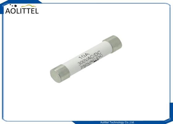
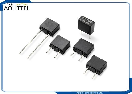
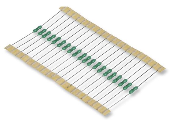
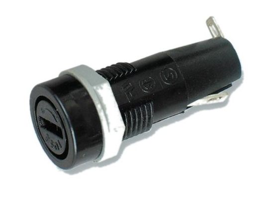
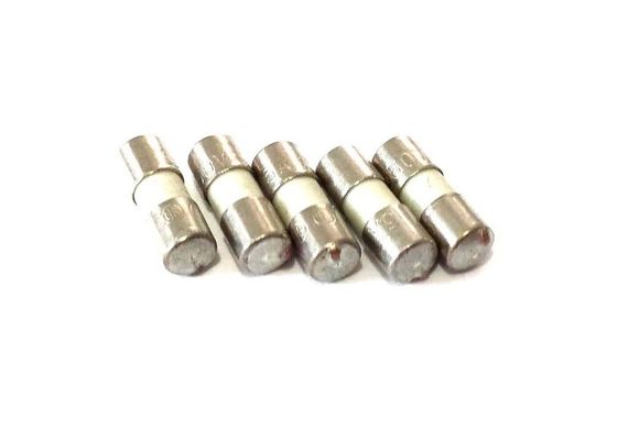
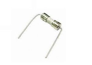
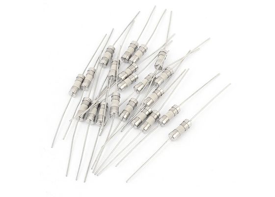
Quick Response Axial Leaded Non-Resettable One Time Ceramic Tube Fuse 2.5A 250VAC With 3.6x10mm Fast Blow Single Cap
Description
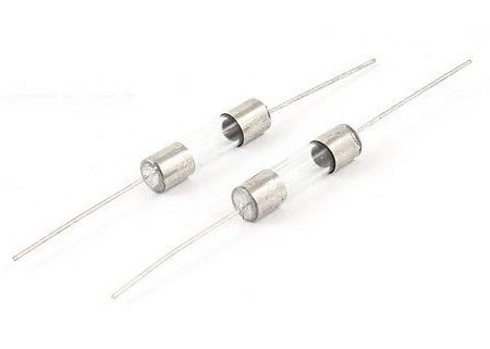
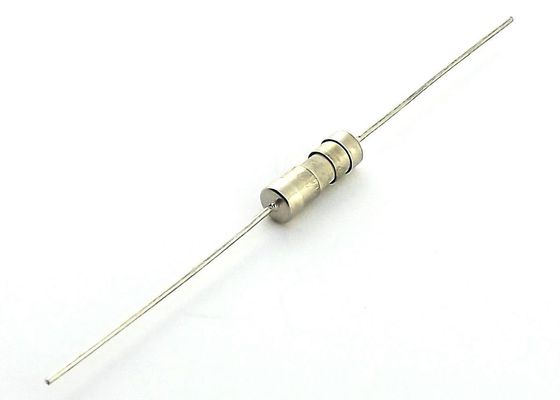
Aolittel HFP fast-acting 3.6 x 10mm axial-leaded fuse constructed with ceramic tube and one-piece nickel-plated endcaps featuring tinned copper axial leads. Small 3.6 x 10mm size offers more design flexibility by doing away with conventional over-capping while providing higher I2t values.
___________________________________________________________ Download________
Operating Characteristics
|
% of Ampere Rating(In)
|
Blowing Time
|
| 100% * In |
4 hours Mi |
| 200% * In |
60 sec Max |
Certifications
|
Voltage Rating
|
Agency
|
Ampere Range
|
Agency File Number
|
| 125V/250V |
UL |
250mA ~ 5A |
E340427(JDYX) |
| C-UL |
250mA ~ 5A |
E340427( JDYX7) |
Specification
|
Part
No.
|
Ampere
Rating
|
Voltage
Rating
|
Breaking
Capacity
|
I2TMelting
Integral(A2.S)
|
Agency Approvals
|
| UL |
cUL |
PSE
|
| HFP 0100A/B |
100mA |
250V/125V |
50A@125V/250VAC |
0.0015 |
○ |
○ |
○ |
| HFP 0125A/B |
125mA |
250V/125V |
50A@125V/250VAC |
0.0025 |
○ |
○ |
○ |
| HFP 0160A/B |
160mA |
250V/125V |
50A@125V/250VAC |
0.0042 |
○ |
○ |
○ |
| HFP 0200A/B |
200mA |
250V/125V |
50A@125V/250VAC |
0.0065 |
○ |
○ |
○ |
| HFP 0250A/B |
250mA |
250V/125V |
50A@125V/250VAC |
0.010 |
● |
● |
○ |
| HFP 0300A/B |
300mA |
250V/125V |
50A@125V/250VAC |
0.018 |
● |
● |
○ |
| HFP 0315A/B |
315mA |
250V/125V |
50A@125V/250VAC |
0.020 |
● |
● |
○ |
| HFP 0350A/B |
350mA |
250V/125V |
50A@125V/250VAC |
0.025 |
● |
● |
○ |
| HFP 0400A/B |
400mA |
250V/125V |
50A@125V/250VAC |
0.035 |
● |
● |
○ |
| HFP 0500A/B |
500mA |
250V/125V |
50A@125V/250VAC |
0.060 |
● |
● |
○ |
| HFP 0630A/B |
630mA |
250V/125V |
50A@125V/250VAC |
0.150 |
● |
● |
○ |
| HFP 0750A/B |
750mA |
250V/125V |
50A@125V/250VAC |
0.350 |
● |
● |
○ |
| HFP 0800A/B |
800mA |
250V/125V |
50A@125V/250VAC |
0.5 |
● |
● |
○ |
| HFP 1100A/B |
1A |
250V/125V |
50A@125V/250VAC |
0.6 |
● |
● |
○ |
| HFP 1125A/B |
1.25A |
250V/125V |
50A@125V/250VAC |
1.2 |
● |
● |
○ |
| HFP 1150A/B |
1.5A |
250V/125V |
50A@125V/250VAC |
1.6 |
● |
● |
○ |
| HFP 1160A/B |
1.6A |
250V/125V |
50A@125V/250VAC |
1.8 |
● |
● |
○ |
| HFP 1200A/B |
2A |
250V/125V |
50A@125V/250VAC |
2.4 |
● |
● |
○ |
| HFP 1250A/B |
2.5A |
250V/125V |
50A@125V/250VAC |
3.2 |
● |
● |
○ |
| HFP 1300A/B |
3A |
250V/125V |
50A@125V/250VAC |
6.0 |
● |
● |
○ |
| HFP 1315A/B |
3.15A |
250V/125V |
50A@125V/250VAC |
7.0 |
● |
● |
○ |
| HFP 1350A/B |
3.5A |
250V/125V |
50A@125V/250VAC |
7.5 |
● |
● |
○ |
| HFP 1400A/B |
4A |
250V/125V |
50A@125V/250VAC |
8.0 |
● |
● |
○ |
| HFP 1500A/B |
5A |
250V/125V |
50A@125V/250VAC |
15 |
● |
● |
○ |
| HFP 1600A/B |
6A |
250V/125V |
50A@125V/250VAC |
24 |
● |
● |
○ |
| HFP 1630A/B |
6.3A |
250V/125V |
50A@125V/250VAC |
28 |
● |
● |
○ |
| HFP 1700A/B |
7A |
250V/125V |
50A@125V/250VAC |
36 |
● |
● |
○ |
| HFP 1800A/B |
8A |
250V/125V |
50A@125V/250VAC |
38 |
● |
● |
○ |
| HFP 2100A/B |
10A |
250V/125V |
50A@125V/250VAC |
42 |
● |
● |
○ |
| HFP 2150A/B |
15A |
250V/125V |
50A@125V/250VAC |
45 |
○ |
○ |
○ |
Dimension (mm)


|
NO.
|
Part Name
|
Material
|
| 1 |
Cap
|
Nickel Plated Brass
|
| 2 |
Body
|
Non-Transparent Ceramic Tube
|
| 3 |
Fuse element
|
Alloy
|
| 4 |
Lead wire
|
Tin Plated Copper
|
Features
• Single cap, axial leaded, fast-acting fuse
• 3.6 x 10mm physical size
• Ceramic tube, nickel-plated brass endcap construction
• Tinned copper axial leads
• RoHS complaint, lead-free and halogen free
• Designed to UL/CSA 248 Standard
• Fast Acting, Ceramic body fuse in a compact package
• Available in ratings of 0.10 to 15 Amperes
Average Time Current Curves
TIME IN SECONDS

CURRENT IN AMPERES
Temperature Rerating Curve

Installation Recommendations
A: Propose installation way as following picture.
| a. |
Horizontal installation
|
 |
| b. |
Vertical installation
|
 |
|
Recommended Soldering Parameters
|
Solder Pot Temperature: 260℃ Max
Solder Dwell Time: 2~5s
Solder Iron Temperature: 350±5℃
Heating Time: 5s Max
|
Why should the DCR of a fuse be measured at a load of no more than 10% and an ambient temperature of 25°C ?

The internal resistance of a fuse is an index reflecting its consumed power in the circuit. The higher the resistance, the more power consumed. For fuses, two parameters can be used to check this index: voltage drop or cold resistance.

Voltage drop: the voltage drop reading after the fusing element reaches thermal balance under rated current. To measure it, apply rated current to the fuse and wait until the reading is stable. It may take a few minutes. It is a little inconvenient and time-consuming.

Cold resistance: the reading of cold resistance basically under no load condition, easy and fast.

Therefore, the cold resistance method is always preferred for fuse check. The load of less than or equal to 10% means basically no load or heating condition, so there will be no thermal balance process, while the ambient temperature itself has a certain effect on fuse performance. All performance indexes of a fuse are parameters in ordinary atmospheric condition, i.e. 25°C. The cold resistance of a fuse, if not measured under the above-mentioned conditions, may not be accurate.

 Your message must be between 20-3,000 characters!
 Please check your E-mail!
  Your message must be between 20-3,000 characters!
 Please check your E-mail!
