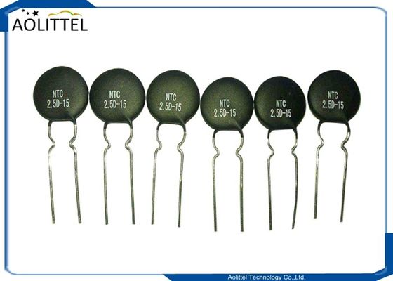
25mm Ceramic Pacakge Photoresistor Photoconductive Cell Light Dependent Resistor LDR 25528 With Light Resistance 10-20K
Applications
Camera Exposure Control
Auto Slide Focus – dual cell
Photocopy Machines – density of toner
Automatic Headlight dimmer
Night Light Control
Street Light Control
Toy
______________________________________________________________________________ Download________
Specification
Diameter: 25mm
Pitch pins: 20mm
Max Voltage: 500V
Max power consumption: 500mW
Operating Temperature: – 30 – +70°C
Item | Type | Max.Voltage (VDC) |
Power Dissipation (mw) |
Ambient Temperature (℃) |
Spectral Response Peak(nm) | Light Resistance (10Lux) KΩ |
Dark Resistance MΩ |
γ |
Response Time |
Illuminance resistance Characteristic |
|
Increase | Decrease | ||||||||||
φ25 Series | GM25516 | 500 | 500 | -30~+70 | 560 | 5-10 | 1 | 0.6 | 30 | 30 | 2 |
GM25528 | 500 | 500 | -30~+70 | 560 | 10-20 | 2 | 0.6 | 20 | 30 | 2 | |
GM25537-1 | 500 | 500 | -30~+70 | 560 | 20-30 | 3 | 0.7 | 20 | 30 | 3 | |
GM25537-2 | 500 | 500 | -30~+70 | 560 | 30-50 | 5 | 0.7 | 20 | 30 | 3 | |
GM25539 | 500 | 500 | -30~+70 | 560 | 50-100 | 8 | 0.8 | 20 | 30 | 4 |
Dimension
unit:mm
Physical and Environmental Characteristics
ITEM | CONDITIONS | PERFORMANCE |
Solderability | Put the terminals into welding tank at temp. 230±5℃ for 2±0.5s (terminal roots are 5mm away from the tin surface). | wetting>95% |
Temperature Changing | Change of temperature in accordance with: TA: -40℃ TB: +60℃ Number of cycles: 5 Exposure duration: 30min | Drift of R10 = ± 20% No visible damage |
Constant humidity and heat | 1. Put the device in test box at Temperature: 60±5℃ Humidity: 90-95% Illumination: 0lux Duration: 100h 2. Take the device and measure after24h at normal temperature and humidity. |
Drift of R10= ± 30% No visible damage |
Constant load Temperature | At 25±5℃ Illumination: 150lux at rated power Duration: 600h | No visible damage |
Wire Terminals Strength | Bend the wire terminal at its root to 90 degree, and then bend it to a opposite direction. | No visible damage |
Vibration | Frequency : 50Hz Swing: 1.5mm with Directions: parallel to ceramic substrate normal to ceramic substrate. Duration:2h | No visible damage |
Photoconductive Cell Typical Application Circuits
General
Light Dependent Resistor is easy to use in projects. It requires a device or circuit to be automatically switched on or off in darkness or light. The resistance will change depending on the intensity of light it is exposed to.
Three material shell:
1.)the epoxy body
2.)the metal body
3.)the glass body
All specification or diameter: 3mm, 4mm, 5mm, 6.5mm, 7mm, 8mm, 10mm, 11mm, 12mm, 20mm, 25mm and so on .
Test Condition
Max. External Voltage: The max. voltage can be consistently imposed in the components in darkness.
Dark Resistance:The resistance which is get from closed the 10 lux light for 10 seconds. Max. Power:When the environment temperature is 25℃ using the biggest power Light Resistance:The resistance which is get after 400-600lux light for 2 hours, test with the standard light (CCT:2854K) 10 lux get the value.
Γ Value: The ratio gets from the standard resistance in 10 lux illuminance and 100lux illuminance’s rate.
Lg (R10/R100)
γ= =Lg(R10/R100)
Lg (100/10)
R10、R100 the resistance value in 10lux and 100 lux respectively. (γ’s tolerance is ±0.1)
Application Board Showcase