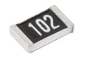
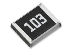
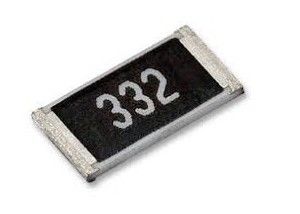
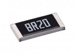
0201 0402 0603 0805 1206 1Ω~2.2MΩ ±1% SMD General Purpose LED Chip Resistor 1Ω~22MΩ±5% 1210 1218 1812 2010 2512
Features
Small size and ligtweight with size range per int'l standard
Aolittel products comply with environmental requirement in accordance with SONY of code no. SS-00259 for not related in 8 harmful materials.
Highly stable in auto-placement surface mounting application
Compatible with both wave soldering and reflow soldering
Configuration
Dimensions ((unit: mm))
Size | L | W | T | C | D |
0201 | 0.60 ±0.03 | 0.30 ±0.03 | 0.23 ±0.03 | 0.15 ±0.05 | 0.15 ±0.05 |
0402 | 1.00 ±0.10 | 0.50 ±0.05 | 0.35 ±0.05 | 0.20 ±0.10 | 0.25 ±0.10 |
0603 | 1.60 ±0.10 | 0.80 ±0.10 | 0.45 ±0.10 | 0.25 ±0.15 | 0.30 ±0.15 |
0805 | 2.00 ±0.10 | 1.25 ±0.10 | 0.50 ±0.10 | 0.35 ±0.20 | 0.30 ±0.20 |
1206 | 3.10 ±0.10 | 1.60 ±0.10 | 0.55 ±0.10 | 0.45 ±0.20 | 0.40 ±0.20 |
1210 | 3.10 ±0.10 | 2.50 ±0.10 | 0.55 ±0.10 | 0.45 ±0.25 | 0.45 ±0.25 |
1218 | 3.10 ±0.10 | 4.60 ±0.10 | 0.55 ±0.10 | 0.45 ±0.25 | 0.45 ±0.25 |
1812 | 4.60 ±0.10 | 3.00 ±0.10 | 0.55 ±0.10 | 0.55 ±0.25 | 0.50 ±0.25 |
2010 | 5.00 ±0.20 | 2.50 ±0.15 | 0.55 ±0.10 | 0.60 ±0.25 | 0.50 ±0.25 |
2512 | 6.35 ±0.20 | 3.10 ±0.15 | 0.55 ±0.10 | 0.60 ±0.25 | 0.60 ±0.25 |
Power Derating Curve
For resistors operated in ambient temperatures above 70℃, power rating must be derated in accordance with the curve below.
Electrical Ratings
Size | 0201 | 0402 | 0603 | 0805 | 1206 | 1210 | 1812 | 1218 | 2010 | 2512 |
Power Rating at 70℃ | 1/20W | 1/16W | 1/10W | 1/8W | 1/4W | 1/3W | 1/2W | 1W | 1/2W | 1W |
Max RCWV | 15V | 50V | 50V | 150V | 200V | 200V | 200V | 200V | 200V | 200V |
Max Overload Voltage | 30V | 100V | 100V | 300V | 400V | 400V | 400V | 400V | 400V | 400V |
Jumper<50mΩ | 0.5A | 1A | 1A | 1A | 2A | 2A | 2A | 2A | 2A | 2A |
Operating Temperature Range | -55~+155℃ |
Standard Resistance Range
0Ω | 0~50mΩ |
±1% (E-96) | 1Ω~2.2MΩ |
±5% (E-24) | 1Ω~3.3MΩ for 0201 0402,1Ω~22MΩ for rest size |
*The working voltage is calculated based on the resistance value following the formula of V=√(P*R) or to its maximum extent as indicated above.
* The overload voltage is calculated based on the resistance value following the formula of V=2.5√(P*R) or to i maximum extent as indicated above.
Soldering Temperature Curve
Specification And Test Methods
ITEM | SPECIFICATION | TEST METHOD |
Solderability | Over 95% of termination must be covered with solder | JIS C 5201 4.17 / MIL-STD-202G METHOD 208H / IEC 60115-1 4.17 Reflow Soldering:Bath temperature:(235±5)℃,Immersion time:(2±0.5)s WAVE Soldering:Bath temperature:(270±10)℃,Immersion time:(2±0.5)s |
Resistance to Solder Heat | J,G: △ R ≦ ±(1% + 0.1Ω) F: △R≦±(0.5% + 0.05Ω) No mechanical damage | JIS C 5201 4.18 / MIL-STD-202G METHOD 210F / IEC 60115-1 4.18 The temperature of the solder bath shall be (260±5)℃,The immersion time shall be(5±0.5)s or(10±1)s as prescribed by the detail specification |
Temperature Coefficient of Resistance :(TCR) |
(0402 & 0201):1Ω~10Ω;>3.3M:±400ppm/℃10Ω(excluding 10Ω)~3.3M: ±200ppm/℃ |
JIS C 5201 4.8 / MIL-STD-202G METHOD 304 / IEC 60115-1 4.8 |
Short time overload | J,G: △ R ≦ ±(2% + 0.1Ω) F: △ R ≦ ±(1% + 0.05Ω) |
JIS C 5201 4.13/IEC 60115-1 4.13 |
Load Life Humidity |
J,G: △ R ≦ ±(3% + 0.1Ω) |
JIS C 5201 4.24/MIL-STD-202G Method 106G / IEC 60115-1 4.24 |
Load Life | J,G: △ R ≦ ±(3% + 0.1Ω) F: △ R ≦ ±(1% + 0.05Ω) |
JIS C 5201 4.25/MIL-STD-202G Method 108A / IEC 60115-1 4.25 |
Temperature Cycle | J,G: △ R ≦ ±(1% + 0.1Ω) F: △R≦±(0.5% + 0.05Ω) No mechanical damage |
JIS C 5201 4.19/MIL-STD-202G Method 107G /IEC 60115-1 4.19 |
Insulation Resistance | Between termination and coating must be over 1000MΩ |
JIS C 5201 4.6 / MIL-STD-202G Method 302 / IEC 60115-1 4.6 |
Bending Strength | J,G: △ R ≦ ±(1% + 0.1Ω) F: △R≦±(0.5% + 0.05Ω) No mechanical damage |
JIS C 5201 4.33 / MIL-STD-202G Method 211A / IEC 60115-1 4.33 |
Markings
1.1 No markings on 0201 and 0402. Markings on the other sizes are expressed by a 3-digit code in its exact value.E. G. : 6R8=6.8Ω;100=10×100 =10Ω;472=47×102 =4700Ω=4.7KΩ.
1.2
a. Markings on sizes 0805, 1206 and above are expressed by a 4-digit code.
E. G. :82R5=82.5Ω;1000=100×100 =100Ω;2212=221×102 =22100Ω=22.1KΩ.
b. Markings on 0603 ±1%( IEC E–96 Series ) are expressed by a 3-digit code; the first two digits represent the value code and the last capital letter represents the multiplier.
The coding system of the E-96 series is as follows :
Resistance | Code |
100 | 01 |
102 | 02 |
105 | 03 |
107 | 04 |
Multiplier code
Code | A | B | C | D | E | F | G | X | Y | Z |
Multiplier | 100 | 101 | 102 | 103 | 104 | 105 | 106 | 10-1 | 10-2 | 10-3 |
E. G. :01Y=100× 10-2=1Ω;68A=499×100 =499Ω;02D=102×103 =102KΩ
c.Any resistance values of 1% tolerance but not included in the E-96 series, the value markings are the same as +/-5% tolerance with labelling identification. E. G.:120=12×100 =12Ω;475=47×105 =4.7MΩ.
d.Marking of the 0 Ohm resistor is a '0' with its value range from 0-50mΩ. No tolerance shown on the product label.
Package quantity
Size | Packaging Q'ty |
0201 | 10Kpcs/Reel |
0402 | 10Kpcs/Reel |
0603 | 5Kpcs/Reel |
0805 | |
1206 | |
1210 | |
1218 | 4Kpcs/Reel |
1812 | |
2010 | |
2512 |
Storage Condition
Temperature:10~30℃
Humidity:30%-75%
Storage Time : 1 year