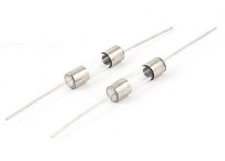
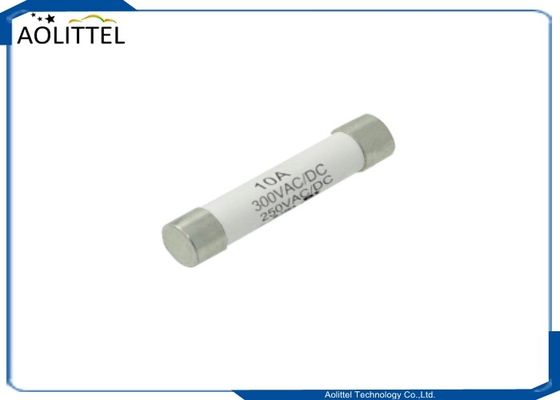
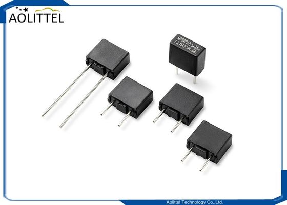
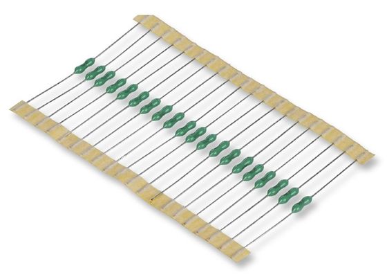
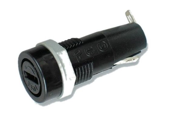
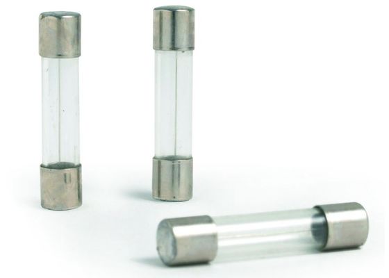
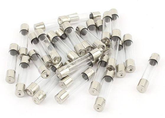
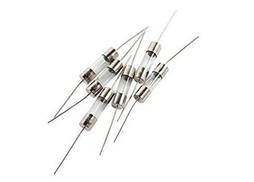
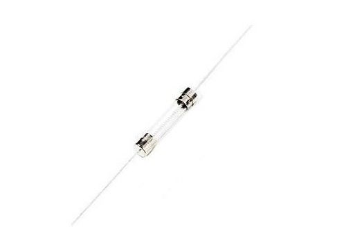
6.35x30mm Quick Blow Fast Acting Car Glass Tube Fuse 6.3Amp 250VAC 125VAC For Inline PCB Mount Fuse Holder Clip
Product Features
| Materials |
Body :glass tube
Lead :tinned copper wire
Cap :brass with nickel plated
Element :alloy
|
| Operating Temperature |
-55℃ to +125℃ (consider de-rating ) |
| Solderability |
260℃, ≤ 3s. (wave )
350±10℃, ≤ 3s. (soldering iron )
|
| Resistance to Soldering Heat |
260℃, 10s. (wave )
350℃, 5s. (soldering iron ) |
| Recommended Soldering Parameters |
Wave soldering parameter
Soldering pot temperature :260℃ Max
Solder dwell time :2∼5s
Hand welding parameter
Soldering iron temperature :350±5℃
Solder dwell time :5s Max.
|
| Storage Conditions |
Can be stored for 3 years under tight seal condition at temperature of +10℃~60℃, relative humidity ≤ 75%.
At most can be kept 30 days at temperature +10℃~60℃, relative humidity ≤ 95% under covered conditions.
|
| Standards |
In accordance with UL 248 -1 / -14. |
___________________________________________________________ Download________
Certification
|
Voltage Rating
|
Agency
|
Ampere Range
|
Agency File Number
|
| 125V/250V |
UL |
100mA ~ 30A |
E340427 |
| C-UL |
100mA ~ 30A |
E340427 |
Performances
|
Part
No.
|
Ampere
Rating
|
Voltage
Rating
|
Breaking
Capacity
|
I2TMelting
Integral(A2.S)
|
Agency Approvals
|
| UL |
cUL |
| MFC0100A/B |
100mA |
250V/125V |
10000A@125 V AC (100mA~10A);
35A@250V AC (100mA~1A);
100A@250V AC (1.25A~3.5A);
200A@250V AC (4A~10A).
|
0.003 |
● |
● |
| MFC0160A/B |
160mA |
250V/125V |
0.008 |
● |
● |
| MFC0200A/B |
200mA |
250V/125V |
0.02 |
● |
● |
| MFC0250A/B |
250mA |
250V/125V |
0.026 |
● |
● |
| MFC0300A/B |
300mA |
250V/125V |
0.047 |
● |
● |
| MFC0315A/B |
315mA |
250V/125V |
0.055 |
● |
● |
| MFC0350A/B |
350mA |
250V/125V |
0.072 |
● |
● |
| MFC0400A/B |
400mA |
250V/125V |
0.10 |
● |
● |
| MFC0500A/B |
500mA |
250V/125V |
0.16 |
● |
● |
| MFC0600A/B |
600mA |
250V/125V |
0.25 |
● |
● |
| MFC0630A/B |
630mA |
250V/125V |
0.28 |
● |
● |
| MFC0750A/B |
750mA |
250V/125V |
0.49 |
● |
● |
| MFC0800A/B |
800mA |
250V/125V |
0.60 |
● |
● |
| MFC1100A/B |
1A |
250V/125V |
0.8 |
● |
● |
| MFC1125A/B |
1.25A |
250V/125V |
1.6 |
● |
● |
| MFC1150A/B |
1.5A |
250V/125V |
2.5 |
● |
● |
| MFC1160A/B |
1.6A |
250V/125V |
3.2 |
● |
● |
| MFC1200A/B |
2A |
250V/125V |
5.6 |
● |
● |
| MFC1250A/B |
2.5A |
250V/125V |
7.6 |
● |
● |
| MFC1300A/B |
3A |
250V/125V |
14 |
● |
● |
| MFC1315A/B |
3.15A |
250V/125V |
19 |
● |
● |
| MFC1350A/B |
3.5A |
250V/125V |
20 |
● |
● |
| MFC1400A/B |
4A |
250V/125V |
25 |
● |
● |
| MFC1500A/B |
5A |
250V/125V |
42 |
● |
● |
| MFC1600A/B |
6A |
250V/125V |
80 |
● |
● |
| MFC1630A/B |
6.3A |
250V/125V |
96 |
● |
● |
| MFC1800A/B |
8A |
250V/125V |
200 |
● |
● |
| MFC2100A/B |
10A |
250V/125V |
320 |
● |
● |
| MFC2120A/B |
12A |
250V/125V |
470 |
● |
● |
| MFC2150A/B |
15A |
250V/125V |
650 |
● |
● |
| MFC2200A/B |
20A |
250V/125V |
870 |
● |
● |
| MFC2250A/B |
25A |
250V/125V |
1320 |
● |
● |
| MFC2300A/B |
30A |
250V/125V |
1820 |
● |
● |
Dimension (mm)
| Axial leaded |
 |
| With lead |
 |
Operating Characteristics
|
% of Ampere Rating(In)
|
Blowing Time
|
| 100%* In |
4 hours Min |
| 135%* In |
1 hour Max |
| 200%* In |
60 sec Max |
Actual Product Photos


How select fuse ?
Fuses are overcurrent protection devices that used for three primary purposes: - To prevent damage to electronic and electrical equipment. - To provide safety for equipment users and personnel. - To isolate subsystems from the main system after an over current occurs. Fuses are designed to allow electric currents to safely flow during normal operation but will quickly open when an over-current situation develops.
Overcurrents
There are typically two types of overcurrents; short circuits and overloads. Overcurrents exist when the normal load for a circuit is exceeded.
An overload is any current flowing within the normal circuit path that is higher than the circuit normal full load current.
A short circuit is an overcurrent which greatly exceeds the normal full load current of the circuit. Also, as the name infers, a short circuit leaves the normal current carrying path of the circuit and takes a "short-cut" around the load and back to the power source.
Components and equipment can be severely damaged by both types of overcurrents. Fuses are used not to prevent overcurrents but rather to protect components, equipment and people when overcurrents do occur.
Fuse Characteristics
Fuses are classified by the different fuse characteristics. These defining characteristics include:
- Physical size
- Interrupting Ratings
- Construction
- Opening Speed
- Electrical Ratings
- Safety Agency Approvals
Physical Size
Electronic fuses are available in a variety of sizes and shapes as predetermined by the user’s applications. The more popular fuse sizes include 1/4" x 1 1/4" (6.3 x 32.1 mm), 5 x 20 mm, 5 x 15 mm, 13/32" x 1 1/2" (10.3 x 38 mm) as well as special use fuses such as surface mount, telecom indicating, and automotive type fuses.
Construction
Electronic fuses are constructed with many different material types. The most cost effective of the materials is a glass tube, however, when higher voltages or interrupting rating are desired, then stronger materials such as ceramic or glass melamine tubes must be used. Plastic housings are typically used in low voltage automotive fuse construction.
Electrical Ratings
Typically each fuse has two different electrical ratings:
Voltage and Current.
Voltage Rating
The voltage rating of a fuse refers to the maximum voltage that a fuse may be subjected to for safe operation. Fuses are typically marked for A/C Voltage but may also carry a D/C Voltage rating as well.
Current Rating
The current rating of a fuse must be selected as to adequately protect a circuit without causing "nuisance" openings. Generally, fuses should be selected at 125% of the steady state RMS or DC current of the circuit at 25° C. Higher ambient temperatures may cause the fuse to open prematurely; therefore fuse de-rating may be necessary in those applications. Please consult the Optifuse factory for de-rating specifications.
Additional consideration must be given to circuits with potential "inrush currents". Inrush currents are created by switching, capacitive loads or in motor or transformer applications. This in-rush may be many times the circuit’s normal full load amperes. Time delay fuses should be selected for these applications.
Interrupting Ratings (Breaking Current)
The interrupting rating of the fuse is the maximum current that the fuse can safely open at the rated voltage without rupturing or breaking the fuse casing. Stronger materials such as ceramic or glass melamine offer the greatest amount of interrupting capabilities.
Opening Speed
When specifying fuses, careful consideration must be made for the protection of the other circuit elements. Typically, the more sensitive the circuit, the more protection will be necessary for adequate component protection. Fast acting fuses offer higher protection but may not be suitable for circuit with in-rush currents. Circuits with in- rush currents should be protected with time-delay fuses to prevent nuisance openings.
Agency Approvals
Worldwide safety agencies, such as Underwriter’s Labs (U.L.), provide test specifications and test fuses and fuse-accessories under these specifications. Each worldwide safety agency will have its own specifications (such as the test specifications used for testing 5 x 20 mm fuses).
At U.L., if a test specification is available and the fuse passes these tests, then the fuse will be listed under this standard. If a test specification is not available, then the fuse may still be tested (using the manufacturers specifications) by U.L. but will receive U.L. recognition rather than U.L. listing.
International Electrotechnical Commission (IEC) writes the standards followed by many European and Asian countries. Because the electrical characteristics of these fuses are so different, UL/CSA and IEC rated fuses are not characteristically interchangeable.
Fuse Mounting
All fuses must be mounted into a circuit either by directly soldering them on a printed circuit board (PCB), or by using a fuseholder or fuseclips. Directly soldering fuses to a PCB allows for some cost reduction while using holders or clips allows for field replacements. Please consult the OptiFuse factory for direct soldering specifications.

 Your message must be between 20-3,000 characters!
 Please check your E-mail!
  Your message must be between 20-3,000 characters!
 Please check your E-mail!
