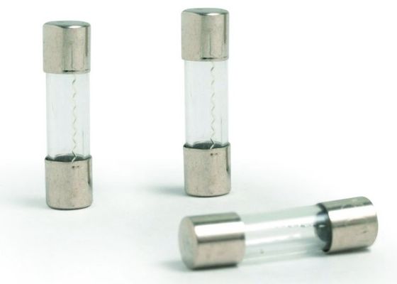
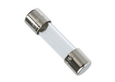
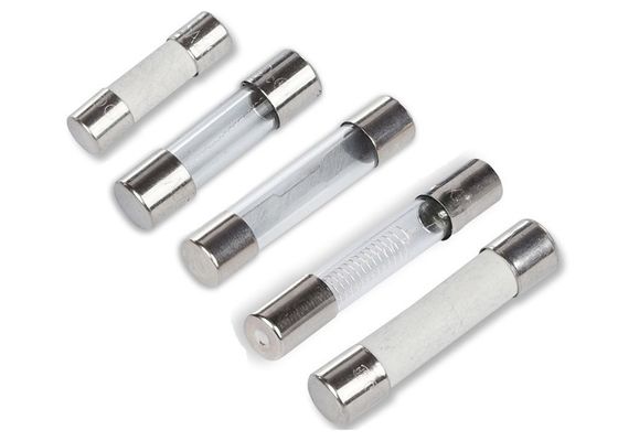
8AG Cylindrical Cartridge Fuses AGX 250VAC 500mA 6X25mm Fast Acting Glass Tube Fuse With 6.25 mm x 25 mm Fast Speed
Features
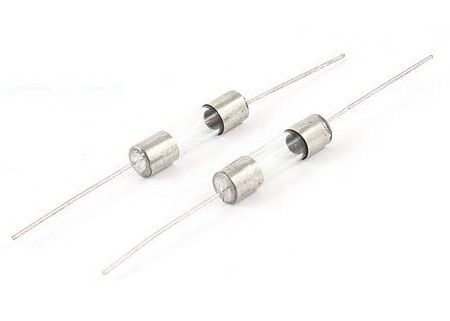
Fast-acting glass tube fuse
1/4" x 1" (6.3 x 25.4mm) physical size
Glass tube, nickel-plated brass endcap construction
For instruments, electronic and small appliance circuits
UL Listed product meets standard 248-14
___________________________________________________________ Download________
Electrical Characteristics
|
% of Ampere Rating(In)
|
Blowing Time
|
| 100%* In |
4 hours Min |
| 135%* In |
1 hour Max |
| 200%* In |
5 sec Max |
Specification
|
Part.
No.
|
Ampere
Rating
|
Voltage
Rating
|
Breaking
Capacity
|
I2TMelting
Integral(A2.S)
|
| MFC0100A/B |
100mA |
250V/125V |
10000A@125 V AC (100mA~10A);
35A@250V AC (100mA~1A);
100A@250V AC (1.25A~3.5A);
200A@250V AC (4A~10A).
|
0.003 |
| MFC0160A/B |
160mA |
250V/125V |
0.008 |
| MFC0200A/B |
200mA |
250V/125V |
0.02 |
| MFC0250A/B |
250mA |
250V/125V |
0.026 |
| MFC0300A/B |
300mA |
250V/125V |
0.047 |
| MFC0315A/B |
315mA |
250V/125V |
0.055 |
| MFC0350A/B |
350mA |
250V/125V |
0.072 |
| MFC0400A/B |
400mA |
250V/125V |
0.10 |
| MFC0500A/B |
500mA |
250V/125V |
0.16 |
| MFC0630A/B |
630mA |
250V/125V |
0.28 |
| MFC0750A/B |
750mA |
250V/125V |
0.49 |
| MFC0800A/B |
800mA |
250V/125V |
0.60 |
| MFC1100A/B |
1A |
250V/125V |
0.8 |
| MFC1125A/B |
1.25A |
250V/125V |
1.6 |
| MFC1150A/B |
1.5A |
250V/125V |
2.5 |
| MFC1160A/B |
1.6A |
250V/125V |
3.2 |
| MFC1200A/B |
2A |
250V/125V |
5.6 |
| MFC1250A/B |
2.5A |
250V/125V |
7.6 |
| MFC1300A/B |
3A |
250V/125V |
14 |
| MFC1315A/B |
3.15A |
250V/125V |
19 |
| MFC1350A/B |
3.5A |
250V/125V |
20 |
| MFC1400A/B |
4A |
250V/125V |
25 |
| MFC1500A/B |
5A |
250V/125V |
42 |
| MFC1600A/B |
6A |
250V/125V |
80 |
| MFC1630A/B |
6.3A |
250V/125V |
96 |
| MFC1800A/B |
8A |
250V/125V |
200 |
| MFC2100A/B |
10A |
250V/125V |
320 |
| MFC2120A/B |
12A |
250V/125V |
470 |
| MFC2150A/B |
15A |
250V/125V |
650 |
| MFC2200A/B |
20A |
250V/125V |
870 |
| MFC2250A/B |
25A |
250V/125V |
1320 |
| MFC2300A/B |
30A |
250V/125V |
1820 |
Dimensions - mm

Time-Current Curves

Testing for a Blown Fuse

Whilst it is easy to visually inspect the element in a glass fuse to see if it has blown, the majority of fuses have solid, non-transparent bodies that hide the element from view. To test if the fuse is blown, we require a multimeter. Once configured, a multimeter can measure the resistance of the fuse element. Resistance is measured in Ohms 'Ω'. The following tutorial uses a digital multimeter, however the same principles apply when using an analogue multimeter (ie. one with a needle display). If you are using an analogue meter, firstly read the tutorial and then refer to the additional notes at the end.
1. Connecting the Test Leads.
The black lead should be connected to the Common socket.
The red lead should be connected to the Ω or Ohms socket.
2. Selecting the Correct Setting.
Move the dial to the lowest range of the Ohms scale (200 ohms is the lowest setting on this mulitmeter). This should also power the meter ON. If there is a seperate ON switch, please turn the meter ON. You can see in the picture that the Ohms range is illustrated by a light green band in lower left area.
The 5 different Ohms range settings on this multimeter are;
2M = 2,000,000 ohms or 2 Megaohms (highest resistance setting)
200k = 200,000 ohms
20k = 20,000 ohms
2k = 2,000 ohms
200 = 200 ohms (lowest resistance setting)
3. Check the Meter is Working.
Touch the metal tips of the 2 testing leads and whilst holding them together, the meter display should change to show that little or no resistance is present. Power will simply flow from one lead back through the other. When you seperate the two tips, the meter display will return to a 100% resistance state.
4. Measure the Fuse.
Important! Place the fuse on a non-conducting surface such as wood, laminate or plastic. Touch the metal caps at each end of the fuse with the metal tips of the testing leads. There is no polarity so you can use any lead for either fuse cap. Ensure to make good contact by touching a clean metal surface on each cap. Whilst the leads are firmly connected to the fuse, look at the reading displayed on the multimeter.
Note: If you wish to test a fuse still located in a circuit. Please ensure that you have turned off power and disconnected the power source to avoid possibility of electric shock.
5. Understanding the Reading.
Fuse is OK: If the meter reading changes to a low resistance value (similar to the result of touching the 2 leads together).
Fuse is Blown: If the meter reading does not change and display still shows the original 100% resistance state.
Don't forget to turn the multimeter OFF when you have finished testing.
How to use an Analogue Multimeter.
Analogue multimeters provide readings by moving a needle over a fixed scale. The testing process is exactly the same.
Choose the correct Ohms range & touch the metal tips of the testing leads together. The need will 'sweep' across the scale to show little to no resistance. A good fuse will generate the same reading.
When the tips are seperated, the needle will show 100% resistance state. A blown fuse will generate the same reading. Make sure that the testing lead tips make a good connection to the metal end caps of the fuse and the fuse is tested on a non-conducting surface.

 Your message must be between 20-3,000 characters!
 Please check your E-mail!
  Your message must be between 20-3,000 characters!
 Please check your E-mail!

