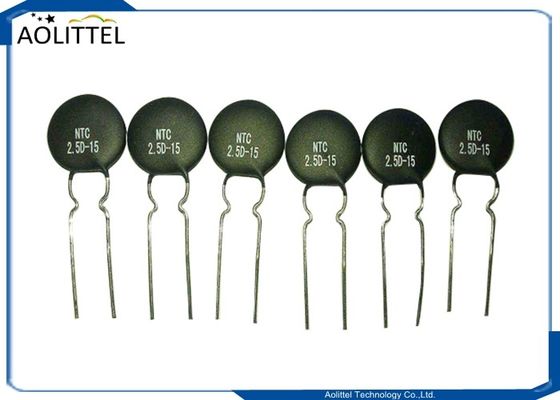
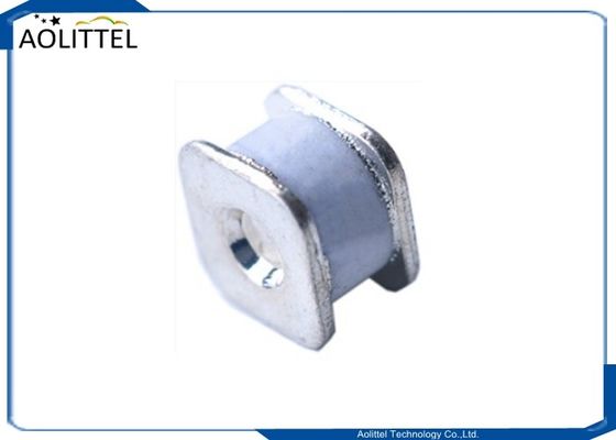
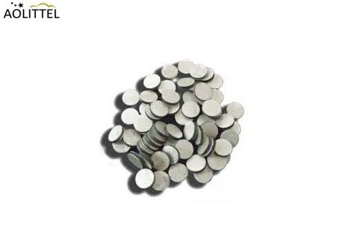
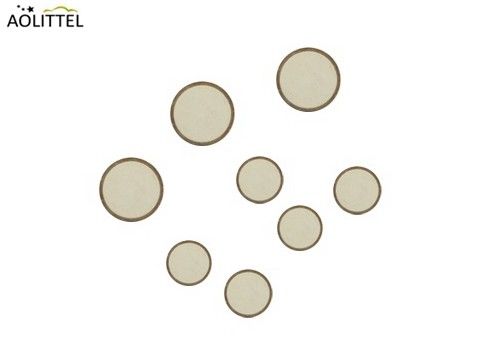
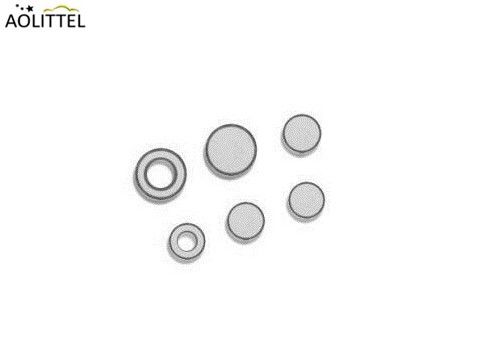
4.8mm Diameter Leadless Bare Disc NTC Thermistor 520 Ohm 10% 2850K For Automotive Temperature Sensor
General
Aolittel leadless disc thermistors offer excellent thermal and electrical stability with wide range of resistance values customizable based on material properties and customer requirements. These parts are ideal for various general purpose and automotive (AEC-Q200) applications. Available in custom disc sizes and multiple temperature stability options.
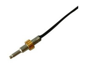
This type of product is widely used in automotive and consumer applications. They are assembled in custom-probes for sensing the temperature of liquids (water, oil, ...), gases or surface of any other component. The metallization covers completely the surfaces of the thermistor. The particularly flat and smooth surfaces ensure an excellent electrical and thermal contact under pressure.
______________________________________________________________________________ Download________
Dimension

| Part Number |
D(mm) |
T(mm) |
| MF12-521K |
4.6-5.0 |
1.1-1.3 |
Main Electrical Property
| Zero Power Resistance at 25℃ |
520±10% Ω |
| Beta Value |
2850±3% 0K |
| Dissipation Factor (δ) |
≥4.5mw/℃ |
| Thermal Time Constant(t) |
≤20S |
| Operating Temperature Range |
-40~+125℃ |
Electrical Characteristics
| Item |
Test Requirements and method |
Performance requirements |
| Zero Power Resistance at 25℃ |
Ambient temp. Range:25℃±2℃(TA).Apply with DC voltage but won’t make thermistor heat then test. |
520±10%Ω |
| Beta Value |
Test resistance at 25℃ and 50℃ then calculate B value as below:
B=ln(R25/R50)/(1/298.15-1/323.15)
R25= Resistance at 25.0±0.2℃
R50= Resistance at 50.0±0.2℃
|
2850±3% 0K |
| Thermal Dissipation Constant |
In room temperature, power consumed mw/℃ at every increase 1 degree |
≥4.5mw/℃ |
|
Thermal Time Constant
|
Time takes from initial temperature decline to 63.2% of temperature value (85℃ →47.1℃) |
≤20S |
Mechanical Property
| Item |
Test Conditions & Methods |
Performance requirements |
| Solder-ability |
Molten tin bath temperature:255±5℃
Time :2.0±0.5 s
Immersion depth: 6mm distance from body
|
Free flow and lead solder wetting for good weldability |
| Resistance to soldering heat |
Immersion depth : 6mm away from body
Temperature:350±5℃
Time :3.5±0.5sec
|
△R/R≤±10% |
Environment And Durability Test
| Steady State damp and hot |
Place into environment 40±2℃ temperature ,Humidity 90&sh;95% R.H. for 42 days, take out and place into room temperature for 1h~2h then do test |
No visible mechanical damage
△R/R ≤±20%
|
|
Temp. Cycling Testing
|
5 Cycles as below requested then take out and place into room temperature for 1h~2h then do test
| Temperature(℃) |
Time(min) |
| -40±5 |
30±3 |
| Room Temperature |
15±3 |
| 125±5 |
30±3 |
|
No visible mechanical damage
△R/R ≤±20%
|
| Ceiling type temperature (+ 125 ℃) under the zero dissipation of durability |
Time : 1000h
Appearance inspection
Zero Power Resistance
|
No visible mechanical damage
△R/R ≤±20%
|
Features & Benefits
Fully metalized leadless disc
Multiple temperature stability options
Customized solutions
Application
Automotive
Consumer
Industrial
Package
Packaging quantity
| Part Number |
Inner packing qty(PC/Bag) |
Box packing qty(PC/Box) |
| MF12-521K |
500 |
5000 |
Terms of Transportation
With negative temperature coefficient thermistor boxes allow in any way transport, but avoid the rain, snow, directly or indirectly and mechanical damage.
Strorage Condition
(1)Negative temperature coefficient thermistor is stored in: temperature for 10 ~ + 40 ℃, relative humidity is not more than 80% of the environment;
(2)Should not have acid, alkali and corrosive gas or radiation source, to prevent the oxidation of the electrode, affect the solderability;
(3)Product storage should be sealed packaging.
Storage life
In the above conditions can be stored for one years
DESIGN OF THE THERMISTOR
Choice of the resistances If the application is to measure the temperature around a defined point, a unique nominal resistance can be chosen (for example, among standard values of the ND range products presented on pages 20 to 24). When it is required to measure the temperature over selected ranges T1 –T2 , T2 –T3 , ..., the corresponding resistance R1 , R2 , R3 , ..., must be such that they can be located on the R (T) characteristic of an existing NTC material (for example among standard materials whose R (T) are displayed on pages 29 to 33). The resistances must also be compatible with the resistivity of the material and the dimensions of the thermistor.
Choice of the tolerances
The precision of the temperature measurement determines the calculation of the tolerance on the resistance: R/R = (%/°C). T (°C) For example, the NTC NR55--3049-99, using “N5” material (R (T) characteristic displayed on page 31), requires a precision of 1°C over the temperature range 110°C - 120°C. The tolerances can be calculated: R110°C /R110°C = 1°C* 2.91%/°C = 2.91% R120°C /R120°C = 1°C* 2.76%/°C = 2.76% *For your specific requirements, please consult us.

 Your message must be between 20-3,000 characters!
 Please check your E-mail!
  Your message must be between 20-3,000 characters!
 Please check your E-mail!
