15mm Thermistor PTC 15P 15mm Pitch 5mm 100R 120Degree Thermal Resistor 200mA Green For Telecom AC Circuit
Working Principle
15P (100R) 16P (5R) 19P (100R) MZ126A (12R)
Connect the PTC thermistor in series in the load circuit. When the circuit is in normal working condition, the current through the PTC thermistor is less than the rated current. The PTC thermistor is in the normal state and the resistance is small, which will not affect the normality of the protected circuit. jobs. When the circuit fails, the current greatly exceeds the rated current (2 times of the normal working current), and the PTC thermistor suddenly heats up, showing a high resistance state, so that the circuit is in a relatively "off" state for protection purposes. When the fault is removed, the PTC thermistor automatically returns to a low impedance state and the circuit resumes normal operation.
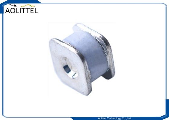
MOUNTING
Can be mounted by force clamping, single side loaded or dual sided. Soldering on the surfaces is not recommended.
APPLICATIONS
• Thermal actuators and valves
• Warming plates
• Vaporizers
• Heaters
Application-Other part
Inverter welding machine is more and more popular in the world since technoloy required for manufacturing, however, good protection can assured inverter welding machine functioning well for long term. We can supply all set of components for overcurrent protection / overvoltage protection. Below is lists we supplying our customers for your ref:
| Varistor |
07D361K
10D471K 10D681K
14D330K 14D151K 14D221K 14D391K
20D820K 20D102K 20D121K 20D121K 20D391K 20D471K
25D431K 25D751K 25D681K 25D821K
32D431K 25D751K 32D681K 32D821K
|
| PTC Thermistor |
126A 15P 16P 16P5R0M265 08M12RM265 05M120-180 19P MZ72-18ROM MZ11-13N13-20 MZ12-16P2R1H140,MZ12-16P4R7H140,MZ11-16P5R0H265,MZ11-16P6R0H265,MZ11-16P7R0H265,MZ11-16P10RH265,MZ11-16P12RH265,MZ72-18RM |
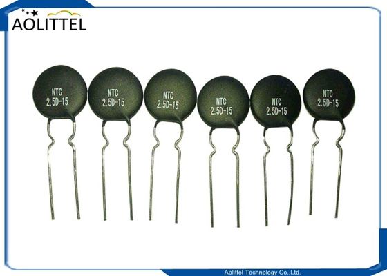
| NTC Thermistor |
2.5D-20 5D-20 8D-20 47D-15 2.5D-15 47D-20 |
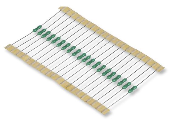
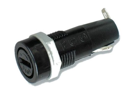
| Fuse |
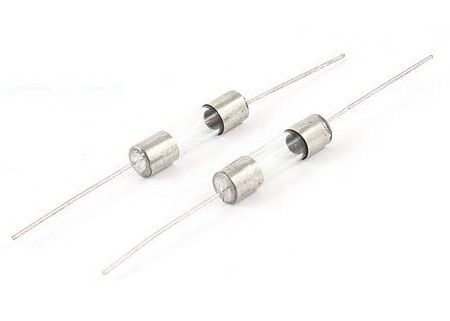
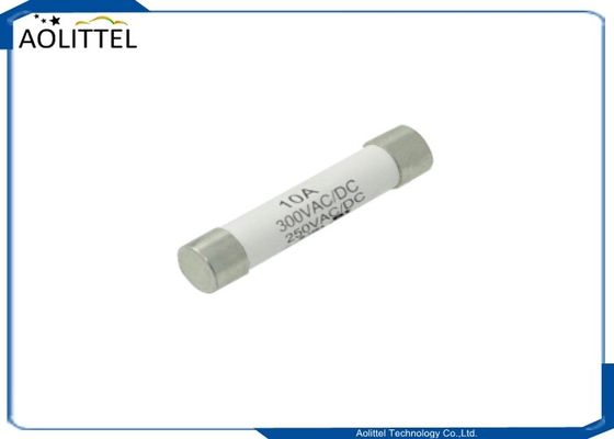
Glass fuse/Ceramic fuse 3.6x10mm/5x20mm/6.35x31.8mm/10x38mm STP/SFP/BTC/BFC/BMT/BMF/PTU/PFU
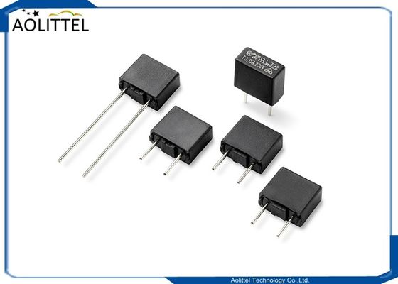
Micro Fuse MTS/MFS/NTS/NFS/TMS/FMS 8x4x8mm
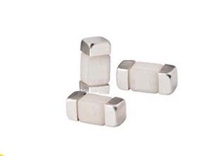
Surface Mount Fuse 6125 2410 SET/SEF/SFE/STE/SST/SSF
|
Dimension (mm)

| Part no |
DMAX |
W±1.0 |
TMAX |
Φd±0.05 |
| 15P(MZ21- P101RNM) |
14.0 |
5 |
7.0 |
0.8 |
Electrical Performances
| Part no |
Rated
resistance
(25℃±1℃)
|
Switch
temperature
(±7℃)
|
Withstand
voltage
Ac
|
Non-operating current
(at 40℃)
|
Typical trip current |
Operating ambient temperature range |
| 15P |
100Ω±25% |
120℃ |
600 V |
100 mA |
200 mA |
-10~+45℃ |
Manufacturing Process
Weighing ⇒ Ball Milling ⇒ Presintering ⇒ Granulation ⇒ Forming ⇒ Sintering ⇒ Add electrode ⇒ Resistance sorting ⇒ Pressure line ⇒ Package insulation ⇒ Assembly ⇒ Withstand voltage detection ⇒ Resistance Inspection ⇒ Final inspection ⇒ Packaging ⇒ Put into warehouse .
Manufacturing Scene
Fuse or PTC?--Protecting against overcurrent incidents
When it comes to overcurrent protection ofelectronic equipment, fuses have long been the standard solution.They come in a wide variety of ratings and mounting styles to fitvirtually any application.
When they open, they completely stop the flow ofelectricity, which may be the desired reaction. The equipment orcircuit is rendered inoperable, which draws the user’sattention to what may have caused the overload condition so thatcorrective action can be taken.
Nevertheless, there are circumstances andcircuits where autorecovery from a temporary overload without userintervention is desirable. Positive temperature coefficient (PTC)thermistors — also called resettable fuses or polymericpositive temperature coefficient devices (PPTCs) — are anexcellent way of achieving this type of protection.
How a PTC works
A PTC consists of a piece of polymer materialloaded with conductive particles (usually carbon black). At roomtemperature the polymer is in a semicrystalline state and theconductive particles touch each other, forming multiple conductivepaths and providing low resistance (generally about twice that of afuse of the same rating).
When current passes through the PTC itdissipates power (P = I2R) andits temperature increases. As long as the current is less than itsrated hold current (Ihold), thePTC will remain in a low-resistance state and the circuit willoperate normally.
When the current exceeds the rated trip current(Itrip), the PTC heats upsuddenly. The polymer changes to an amorphous state and expands,breaking the connections between the conductive particles.
This causes the resistance to increase rapidlyby several orders of magnitude and reduces the current to a low(leakage) value just sufficient to keep the PTC in thehigh-resistance state — generally from around tens toseveral hundred milliamps at rated voltage (Vmax). When the power is shut off thedevice cools down and returns to its low-resistance state.
PTC and fuse parameters
Like a fuse, a PTC is rated for the maximumshort-circuit current (Imax) itcan interrupt at rated voltage. Imax for a typical PTC is 40 A, and mayreach 100 A. Interrupt ratings for fuses of the sizes that may beused in the sorts of applications we are considering here can rangefrom 35 to 10,000 A at rated voltage.
The voltage rating for a PTC is limited. PTCsfor general use are not rated above 60 V (there are PTCs fortelecom application with 250 and 600 V interrupting voltage, buttheir operating voltage is still 60 V); SMT and small-cartridgefuses are available with ratings from 32 to 250 V or more.
The operating current rating for PTCs ranges toabout 9 A, while the maximum level for fuses of the typesconsidered here can exceed 20 A, with some available to 60 A.
The useful upper temperature limit for a PTC isgenerally 85C, while the maximum operating temperature forthin-film SMT fuses is 90C, and for small-cartridge fuses is 125C.Both PTCs and fuses require derating for temperatures above 20C,although PTCs are more sensitive to temperature.
When designing in any overcurrent protectivedevice, be sure to consider factors that may affect its operatingtemperature, including the effect on heat removal of leads/traces,any air flow, and proximity to heat sources. The speed of responsefor a PTC is similar to that of a time-delay fuse.
Common PTC applications
Much of the design work for personal computersand peripheral devices is strongly influenced by the Microsoft andIntel System Design Guide which states that “Using a fusethat must be replaced each time an overcurrent condition occurs isunacceptable.” And, the SCSI Standard for this largemarket includes a statement that “....a positivetemperature coefficient device must be used instead of a fuse, tolimit the maximum amount of current sourced.”
PTCs are used to provide secondary overcurrentprotection for telephone central office equipment, customerpremises equipment, alarm systems, set-top boxes, VOIP equipment,and subscriber line interface circuits. They provide primaryprotection for battery packs, battery chargers, automotive doorlocks, USB ports, loudspeakers, and PoE.
SCSI plug-and-play applications that benefitfrom PTCs include the motherboard and the many peripherals that canbe frequently connected to and disconnected from the computerports. The mouse, keyboard, printer, modem, and monitor portsrepresent opportunities for misconnections, and connections offaulty units or damaged cable. The ability to reset aftercorrection of the fault is particularly attractive.
A PTC can protect disk drives from thepotentially damaging overcurrents resulting from excessive currentfrom a power supply malfunction. PTCs can protect power suppliesagainst overloading; individual PTCs can be placed in the outputcircuits to protect each load where there are multiple loads orcircuits.
Motor overcurrents can produce excessive heatthat may damage the winding insulation and for small motors mayeven cause a failure of the very small diameter wire windings. ThePTC will generally not trip under normal motor start up currents,but will act to prevent a sustained overload from causingdamage.
Transformers can be damaged by overcurrentscaused by circuit faults, and the current limiting function of aPTC can provide protection. The PTC is located on the load side ofthe transformer.
Fuse or PTC?
The following procedure will help in selectingand applying the correct component. Help is also available fromdevice suppliers. For unbiased advice it’s wise to lookfor a company that offers both fuse and PTC technology.
1. Define the circuit operating parameterstaking into consideration:
Normal operating current in amperes
Normal operating voltage in volts
Maximum interrupt current
Ambient temperature/rerating
Typical overload current
Required opening time at specific overload
Transient pulses expected
Resettable or one-time
Agency Approvals
Mounting type/form factor
Typical resistance (in circuit):
2. Select a prospective circuit protectioncomponent (See table)
3. Consult the time-current (T-C) curve todetermine if the selected part will operate within the constraintsof the application.
4. Ensure that the application voltage is lessthan or equal to the device’s rated voltage and that theoperating temperature limits are within those specified by thedevice. If using a PTC, thermally derate Ihold using the equation below.
Ihold =derated Ihold
Thermal derating factor
5. Compare the maximum dimensions of the deviceto the space available in the application.
6. Independently test and evaluate suitabilityand performance in the actual application.

 Your message must be between 20-3,000 characters!