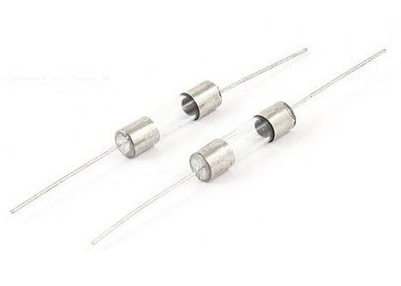
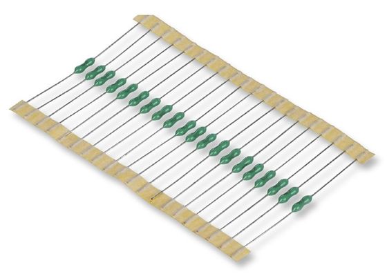
AUPO Pellet Thermal Cutoff Fuse TF Cutoff Circuit Breakers 102℃ 250V 1A P1-1A-F Ceramic Resistive Temperature Fuse
Key Features
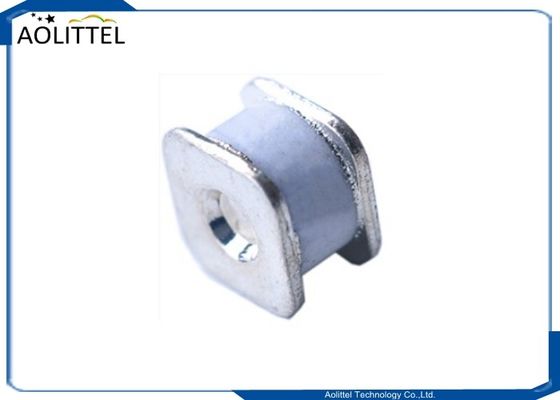
* Type: axial
* Material: ceramic housing
* Rated current: 1A
* Rated voltage: 250V
* Functioning temperature: 102°C
* Certifications: UL, cUL, VDE, CCC, KTL, PSE
* RoHS Directive-compliant and REACH

Dimension
| Series |
Dimension(mm) |
| a |
b |
c |
d |
e |
| P-F |
9.0±0.5 |
38±3 |
Φ0.54±0.5 |
Φ2.5±0.1 |
3.3 or below |
| P-1A-F |
6.5±0.5 |
38±3 |
Φ0.54±0.5 |
Φ2.1±0.1 |
2.4 or below |
Electrical Performances
| Model NO |
Rated functioning temp. |
Fusing-off temperature |
Holding temperature |
Maximum temp .limit |
Rated current |
Rated voltage |
| PN |
(Tf) |
|
(Th) |
(Tm) |
(Ir) |
(Ur) |
| P1-1A-F |
102℃ |
98±2℃ |
80℃ |
200℃ |
1A |
250V |
| P2-1A-F |
115℃ |
112±3℃ |
99℃ |
200℃ |
1A |
250V |
| P3-1A-F |
125℃ |
120±3℃ |
105℃ |
200℃ |
1A |
250V |
| P4-1A-F |
130℃ |
126±2℃ |
107℃ |
200℃ |
1A |
250V |
| P5-1A-F |
135℃ |
131±3℃ |
115℃ |
200℃ |
1A |
250V |
| P9-1A-F |
138℃ |
135±2℃ |
118℃ |
200℃ |
1A |
250V |
| P7-1A-F |
150℃ |
145±3℃ |
128℃ |
200℃ |
1A |
250V |
| P12-1A-F |
145℃ |
140±2℃ |
126℃ |
200℃ |
1A |
250V |
Application
Transformers, Solenoids, Ventilation fans, Electric fans, Small electric motors, Driers, Gas home appliances, Fluorescent lights, Electric shavers, Adaptors, Heating devices, ICs, Batteries, etc. The TCO can also be used for overheating protection.
Design Applications
1. Use the TCO within their specified temperature and electrical ratings.
1) Use the TCO under the maximum operating temperature specified in the individual specification. Using the TCO under a higher temperature than the maximum operating temperature may cause premature open ing or opening delay.
• When the TCO is continuously used at the temperature close to the functioning temperature, the TCO may op er ate while being used.
• When the TCO is continuously used at the temperature higher than the maximum operation temperature, the TCO may be degraded and may not operate normally at the specified temperature.
2) The holding temperature is defined as the highest temperature at which the TCO is activated continuously at the rated current for 168 hours. The TCO can not be used over 168 hours exceeding the holding temperature.
3) Equipment should be designed so that its over shoot does not exceed the maximum temperature limit after the TCO operates.
4) If the TCO is activated by voltage higher than the rated voltage or current higher than the rated current, the TCO produces excessive heat, resulting in premature opening. The arc generated in such operating conditions will result in abnormal appearance (crack on body) and insufficient insulation.
• When TCO is operated in an abnormal mode while the rated voltage and/or the rated current being exceeded, it may not cut off the circuit.
5) Thermal element may be transformed and TCO may open when it is used in the environment from which an excessive temperature change (such as outdoor) is repeated. Investigate the environment where TCO is used.
6) Where transient overload is expected to be applied, repeat the tests under the worst conditions.
7) The TCO cannot be used as a current sensitive fuse.
2. To fully use the function of the TCO, a suitable TCO for each equipment application must be selected.
1) Tests should be repeated for the finished equipment to confirm that the TCO does operate as expected. 2) To improve thermal response of the TCO, put the main body of the TCO and the lead wires(terminals) as close to the heat source as possible and the place where the TCO is evenly heated. If the temperatures transferred to the main body and to the lead wires(terminals) are largely different from each other, defective operation may occur, causing arcing and deterioration of insulation.
3. Avoid application of excessive vibration and mechanical stress to the TCO. Otherwise, failure of the fusible alloy or lead wires, or damage to the main body may occur.
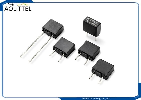
4. The following 1) and 2) are precautions for thin type TCO (MP and MU series)
1) TCO body and terminals must be properly fixed when the TCO is mounted in the equipment. It may cause breaking of thermal element and/or terminals, or damages of the TCO body, or other failure when the body or terminals is not properly connected. Avoid a transport under the condition with a connection only a single side of terminal and the equipment as it might cause breaking of thermal element and/or terminals, or damages of the TCO body, or other failure due to the vibration or mechanical stress on the transportation. 2) When TCO is mounted in the equipment, terminals must be aligned with the body. If TCO body and terminals are mutually mounted askew, it might cause breaking of thermal element and/or terminals. Also after assembling TCO in the equipment, avoid pulling, bending, pushing stress and twisting stress in the TCO body and terminals in order not to cause breaking of thermal element and/or terminals, or damages of the TCO body.
5. When sealing the TCO with resin, select a resin that does not corrode the seals or the lead wires(terminals). When sealing the overall TCO with resin, determine the fixing conditions by repeating the test using your final product to check whether or not the resin properties (e.g. expansion, contraction, and curing temperature) affect the TCO and whether or not the TCO can operate normally.
6. When immersing equipment with a TCO in varnish or solvent and then drying it, repeat the test to check whether or not the varnish or solvent used dissolved the coating of the TCO or caused damage, such as cracks, before performing the treatment again.
7. Do not use under the following environments.
1) In liquids such as water, oil, chemical and organic solvents
2) In direct sunlight, outdoors or in dusty atmospheres
3) In places where water condensation occurs
✽ Use in the following environments may affect the performance of the TCO; Verify performance and reliability be fore production use.
(1) In places full of corrosive gases such as sea breeze, Cl2, H2S, NH3, SO2 and NO2
(2) In environments with high static electricity and/or strong electromagnetic waves.
8. Do not use the TCO in aerospace equipment, atomic energy equipment, military weap ons, life saving equip ment, automobile, etc.

 Your message must be between 20-3,000 characters!