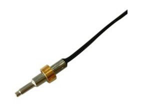
Original Aupo Normal Close Thermally Sensitive Fuse Thermal Cutoff Switch TF 115℃ 250V 10A A2-10A-F TCO Circuit Breaker
Overview
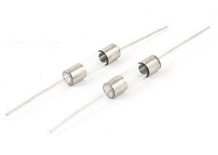
The thermal cutoffs (TCO) are non resetting, thermally sensitive, single pole, normally closed devices and
are intended to be used in various appliances.A temperature sensitive thermal fuse melts and opens electrical
contacts when temperatures exceed the rating of the thermal fuse. Thermal cutoffs are providing protection
against potentially hazardous overheating conditions in billions of products around the world.

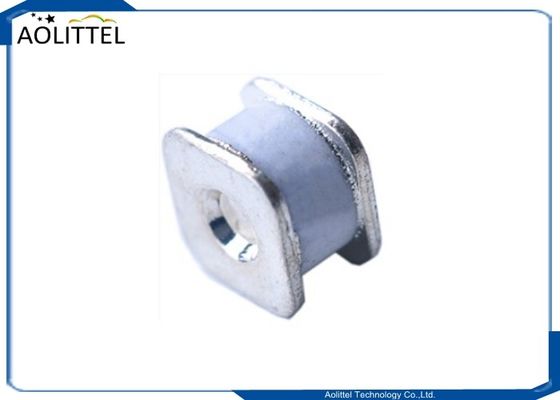
Dimension
Ratings
| Model NO |
Rated functioning temp. |
Fusing-off temp |
Holding temperature |
Maximum temp .limit |
Rated current |
Rated voltage |
In
8/20us
|
Imax 8/20us |
| P/N |
(Tf) |
|
(Th) |
(Tm) |
(Ir) |
(Ur) |
(15 Times) |
(1 Times) |
| A1-10A-F |
102℃ |
98±2℃ |
72℃ |
203℃ |
10A |
250V |
5KA |
10KA |
| A2-10A-F |
115℃ |
112±3℃ |
85℃ |
203℃ |
10A |
250V |
5KA |
10KA |
| A4-10A-F |
130℃ |
126±2℃ |
100℃ |
203℃ |
10A |
250V |
5KA |
10KA |
| A5-10A-F |
135℃ |
131±3℃ |
106℃ |
203℃ |
10A |
250V |
5KA |
10KA |
| A7-10A-F |
138℃ |
135±2℃ |
109℃ |
203℃ |
10A |
250V |
5KA |
10KA |
LEAD FORMING
It is easy to bend the copper lead as it is flexible. But it is likely to be damaged or broken if TCO lead is
repeatedly bent over 90°. When forming the lead, be careful not to apply the forming force direct to TCO
body.
* Forming Sealant Lead Wire
Bend the lead wire at least 4 mm away from the seal. The damage of the sealant worsen the air tightness.
Note that bending is conducted with care, since the worse air tightness impedes the normal operation of TCO.
Holders or tools used during lead forming must not grasp the body, but lead wire. Doing so can protect from
damage to the body of TCO.
* Forming lead wire other than sealed lead
Bend at least 4mm away from TCO body, since excessive force to the body causes the deformation of
TCO case.
PRECAUTION FOR LEAD CONNECTION
* Be careful to be free from damage, burn, nick, crack or overheating at TCO seal or body.If there are such
damage as above, do not use.
* Experimental assembly trials should be made to check the damage of lead wire, seal or TCO body.
* When connecting wire to TCO, it is recommended that splice or terminal shall be used. The material of
splice or terminal should be corrosion resistant.
* When securing the splice or terminal to TCO, be careful not to damage the TCO body. The material of
splice or terminal should be low heat resistace. Be careful not to cause excessive overheating due to poor
connection method. It should be noted that the connection wire shall be flexible standard wire. If using solid
wire, use the bending process.
SOLDERING OF LEAD
The following points should be noted if soldering is used to connect TCO lead.
* Do soldering work on lead as far away from the TCO body if possible.
* Be careful to minimize the heat transfer to TCO body. When proper means to prevent the heat transfer is
not provided, TCO seal or body may be damaged and broken-down.
* Mechanical security must not depend on solder alone.
* Electric current must not pass through inner electric contact or the case of TCO when soldering. The
passing of excess current damages the TCO element or case.
* To shorten the working time, employ pre-soldering process at the intended soldering area.
* Soldering Method to prevent heat.(use heatsink)
* Tensile strength of lead
Pull force shall not be over 2kg and push force shall not be over 0.5 kg.
* Strength of Case Applying the excessive force to tie the case body causes deformation and effects normal operation of TCO. Since this may cause the fuse to not properly operate, be sure to avoid the excessive tying force.
* Functioning Temperature Test Install the TCO in a chamber and gradually increasing temperature upto 20°C lower than Tf, then if the temperature of the chamber and the testing products are made equal, the temperature is increased 1°C per minute, then the fuse will function within the specified tolerance.
* Temperature Increase Test When normal operating voltage and current are applied to the TCO in ambient temperature (20~25) °C the temperature of the TCO will go up.But the increase of temperature shall not be more than 10°C
* Insulation Resistance After having operated in temperature test, the insulation resistance shall be more then 0.2 ohms when tested with 500V resistance measuring machine.
* Contact Resistance Test The resistance of the both leads of the TCO should not exceed 1.5 ohms within the 10mm length of the leads. * Dielectric Voltage Withstand Test After conducting the Insulation resistance test, the TCO shall be maintained without breakdown when AC 500V is applied between the leads of the TCO for 1 Min.
*Aging Test After keeping the TCO at the temperature 20 ± 3 °C lower then the Tf for 48 hours,the TCO shall pass the Functioning temperature test

 Your message must be between 20-3,000 characters!