Customized Power Wireless Charger Coil 7uH 5V Transmitter Receiver Induction Shield For Samsung Apple Smart Mobile Phone
Quick details
Aolittel wireless charging receiving coils/shields and wireless charging transmitter coils/shields feature high permeability shielding and high-saturation powdered iron that is not affected by permanent locating magnets. All the parts are lead (Pb)-free and RoHS-compliant, and some are also AEC-Q200-qualified.

Specifications
| Model |
Picture |
Specification |
| A28-5V Wireless charger coil |
|
OD: 44.8*52.5 mm
ID: 18.5*28.5 mm
Thickness: 1.25H
Turns: 9 TS
Wire diameter: 0.08*105p
Wire: silk-coated wire
Inductance: 7.3 uh
Package: Sucking tray / carton
RoHs/SGS
Winding direction: Clockwise
|
| A11-5V Wireless charging coil |
|
OD: 43±0.5mm
ID: 20.5 mm
Thickness: 1.2mm
Turns: 10 TS,1 Layer
Wire diameter: 0.08*105p
Wire: silk-coated wire
Chip size: 50*5*1.0
Inductance: 3.9 uh
Inductance for add magnet: 6.8 uh
Product size: 50*2.2H
Unit weight: 15g
Package: Sucking tray / carton
RoHs/SGS
|
| Samsung s6 wireless charging and transmitting coil |
|
OD: 43 mm
ID: 20.5 mm
Thickness: 1.2H
Turns: 10 TS
Wire diameter: 0.08*105p
Wire: enamelled wire
Inductance: 6.3 uh
Package: Sucking tray / carton
RoHs/SGS
Winding direction: Clockwise
|
| Apple Watch wireless transmitting coil |
|
Inductance: 7.2 uh
With magnetic sheet
|
|
A11-5V Wireless charging coil
Double wired
Double layer
|
|
OD: 43±0.5mm
ID: 20.5 mm
Thickness: 1.2mm
Turns: 10 TS,2 Layer
Wire diameter: 0.08*105p x 2
Wire: silk-coated wire
Chip size: 50*5*1.0
Product size: 50*2.2H
Unit weight: 15g
Package: Sucking tray / carton
RoHs/SGS
|
| A5 Wireless Charger Coil |
|
OD: 43±0.5mm
ID: 20.5 mm
Thickness: 2.6mm max
Turns: 10 TS,2 layer
Wire diameter: 0.08*105p bifilar
Wire: silk-coated wire
magnetic sheet : 53*53*2.5
Product size:53*53*5.1H
Inductance: 7.3 uh
Package: Sucking tray / carton
RoHs/SGS
Unit weight: 46g
|
| Iphone 6 Wireless Charing coil |
|
OD: 36.*42.7
ID: 27.5*20
Thickness: 0.22H
Turns: 14 TS
Wire dia: 0.13*4p
Wire: Self sticking wire
Inductance: 8.3 uh
Package: Sucking tray / carton
RoHs/SGS
Unit weight: 0.8g
|
| S4 Wireless charging coil |
|
OD: 25.6*36.6
ID: 20.5*10.5
Thickness: 0.41H
Turns: 15 TS
Wire dia: 0.25*2p
Wire: Self sticking wire
Inductance: 12.2 uh
Package: Sucking tray / carton
RoHs/SGS
Unit weight: 1.5g
|
FEATURES
• Wireless charging receiving coil
• For Rx applications up to 10 W
• Optimized for 5 V charging circuitry
• High permeability shielding for wireless charging receiving coils
• Blocks charging flux from sensitive components or batteries
• High saturation powdered iron - not affected by permanent locating magnets
• Durable construction
SHIELD MATERIAL CHARACTERISTICS
• Permeability: approximately 24
• Resistivity: > 10 MW at 100 V
• Core loss: 4000 mW/cc at 500 gauss, 250 kHz
• Magnetic saturation: 50 % at 4000 gauss (to 350 Oe)
Introduction
There are many battery-powered devices, which need to be periodically charged, such as mobile phones, tablets, and battery-powered hand tools. These tools are usually charged by a dedicated cord from a USB port or from a dedicated wall adapter.
Wirelessly transferred power simplifies the charging of these devices and brings more convenience to the everyday lives of our customers. Dedicated controllers are required for wireless charging application control. Freescale provides the Axx family of the dedicated controllers for the wireless charging applications. Each type is intended for a certain range of applications in the automotive or industrial and consumer area. Freescale provides the dedicated wireless charging software library
intended for these controllers. This library maintains all functions required by the Qi specification.
Coil categories
Each application area requires a certain level of power transfer. The main aspects of the categorization are
as follows:
· Transmitter or receiver side:
o The transmitter side generates the power electromagnetic field.
o The receiver side produces the AC/DC current when placed to the power electromagnetic field.
· A level of the transferred power:
o Low power – up to 5 W on the receiver side
o Medium power – from 5 W to 100 W
o High power – from 100 W to 1 kW level
o Very high power – more than 1 kW
· Free-positioning:
o Single coil – with or without an attractor
o Multicoil solution
· Manufacturing:
o Wire wound from the Litz wire
o PCB type of coils
Coil description and properties
The requirements for the coil construction are as follows:
The inductance and power capability must meet the category requirements, including the working frequency and transferring power.
The mechanical dimension must fit to the target application, including the coil area and thickness.
The coil must provide the electromagnetic shielding for the associated electronic device, such as the mobile phone.
Durable construction.
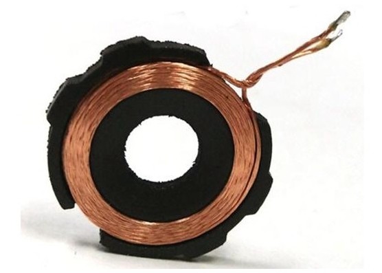
Figure 1 shows the basic wire wound coil structure
Figure 1 Wire wound coil structure (property of TDK)
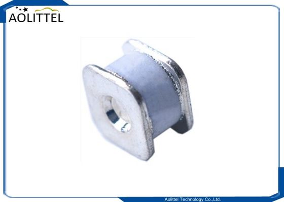
The coil winding can be one or two layers of the Litz wire. The adhesive tape between coil and ferrite
sheet maintains the required distance and the mechanical fixation. The center positioned magnet can be
used to provide better alignment between the transmitter and the receiver coils. The ferrite sheet provides
the one side magnetic shield and forms the magnetic field. The ferrite properties (material and thickness)
have influence to the maximal power transfer for the certain temperature rise.
For the power level 5 W and higher, usually various types of the ferrite material are used. For the power
level lower than 5 W, the thin ferrite tape or other soft magnetic materials could be used. The thickness of
the magnetic shield is from 0.5 mm to 5 mm depending on the type of coil.
A coil has the following properties:
· Inductance ranging from 6 uH to 27 uH.
· The DC resistance depends mainly on the used type of the Litz wire, usually ranging from 20 mΩ to 100 mΩ.
· The dimension depends on the required power transfer capability and the final application, usually ranging from about 30 mm to 55 mm for the rectangular and the circular single coil.
· The working frequency ranges from 105 kHz to 210 kHz for the devices which meet the Qi specification.
· The working voltage is from 5 V to 50 V in extreme conditions.
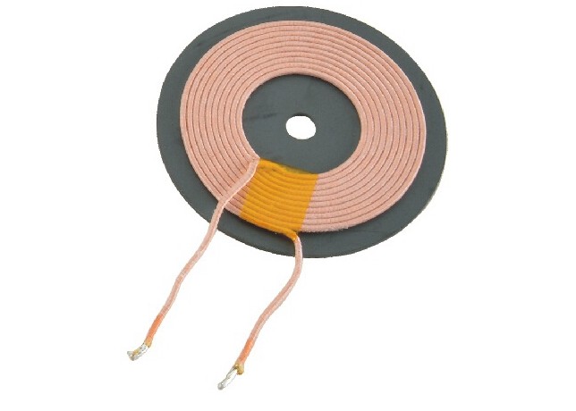
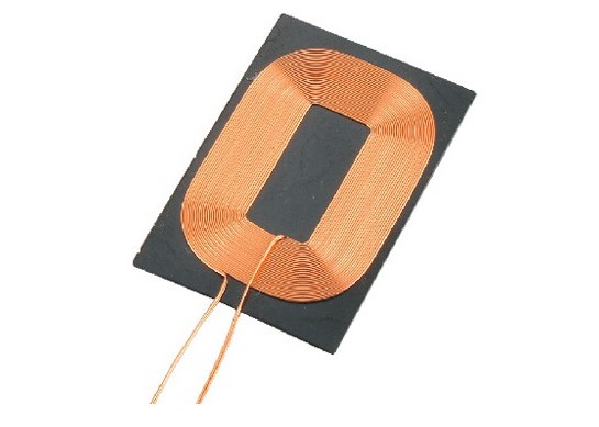
Figure 2 shows the examples of the wire wound coils.
Figure 2 Wire wound coils(property of TDK)
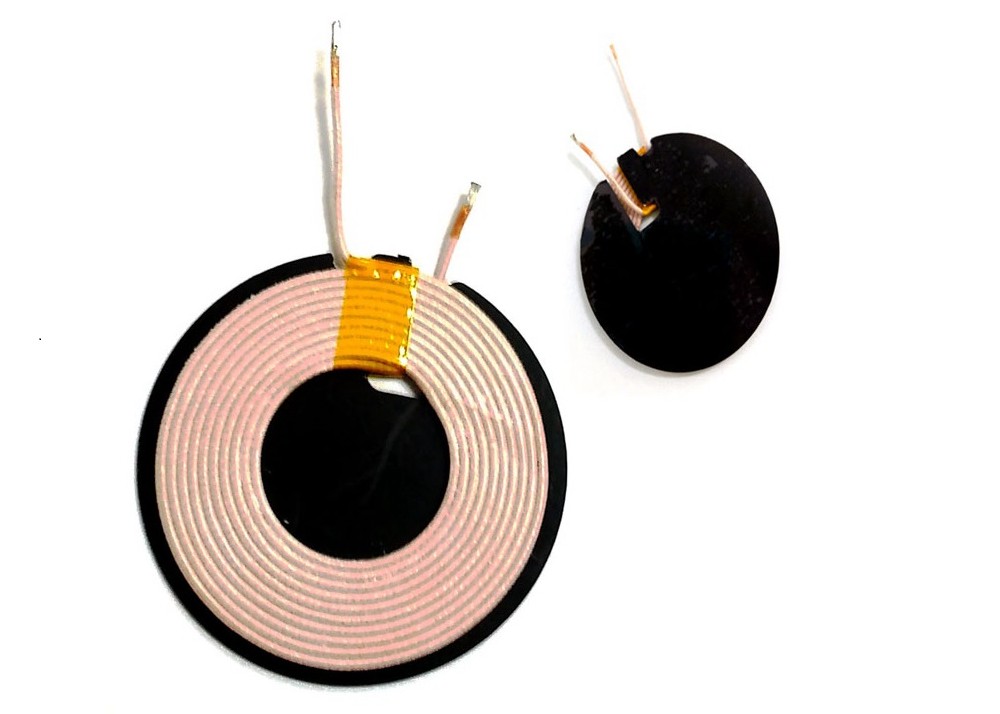
Figure 3 shows the basic PCB coil structure.
Figure 3 Cross section of the PCB coils system
PCB coils consist of several layers of overlapped coils. All coils are independent and have their own connection points. The coil shapes can vary from the rounded square to hexagonal or circular. The PCB coils usually have higher internal DC resistance, lower quality, lower efficiency, lower thickness, and lower cost. They can be combined with wire wound coils.
A Multicoil solution A multicoil solution is used when the free positioning design is required. The transmitter checks each coil coupling to the receiver, and then selects the coil with the best coupling for the power transfer. It can energize one coil only or several coils together. The simultaneously energized coils can provide higher power transfer capability and larger freedom for the receiver coil placement. The simultaneously energized coils are connected to the same AC current source with the same electromagnetic field orientation. The connection can be maintained by the power multiplexer or the separate power drivers can be used for each coil. This type of the power transfer, called as one channel transfer, is intended for one receiver only. If you need to charge two or more devices simultaneously, you need to use the multichannel topology. In this case, each channel works independently. The example of the multicoil design is the Freescale Wireless Charger for automotive sector, topology A13_Rev2. It is controlled by the WCT1001A controller. The final demo example is shown in Figure 4.
Figure 4 Multicoil design example
Figure 5 shows the block schematic of the power multiplexer.
The multiplexer is controlled by the wireless charging controller and it can connect one or more coils from the three-coil set to the energy source. The power multiplexer can be spread to more segments to control multicoil. Then one or more coils can be energized simultaneously. This design can be used for all multicoil topologies by the Qi specification.
Figure 6 shows the next possible topology for the multicoil system.
Figure 6 Independent bridge drivers
This topology uses several bridge drivers to energize each coil. The half or full-bridges are controlled by the wireless charging controller. It is possible to energize one or more coils simultaneously. The selection of the final topology depends on the transferring power level and finally on the cost. If a design requires the EMI filter and small frequency range (automotive sector), the multiplexer can be a better selection.
Conclusion
The use of the A or other controllers from the A family, together with the binary wireless charging library considerably simplifies the whole design process and provides fully tested functions for a reliable application.

 Your message must be between 20-3,000 characters!